- Guide: Fishbone Diagram

Daniel Croft
Daniel Croft is an experienced continuous improvement manager with a Lean Six Sigma Black Belt and a Bachelor's degree in Business Management. With more than ten years of experience applying his skills across various industries, Daniel specializes in optimizing processes and improving efficiency. His approach combines practical experience with a deep understanding of business fundamentals to drive meaningful change.
- Last Updated: October 19, 2023
- Learn Lean Sigma
The Fishbone Diagram, also known by various other names such as Ishikawa Diagram, Cause and Effect Diagram or 6Ms, is a visual tool used in problem-solving and root cause analysis . Originating from the quality management sector, it is used as a systematic approach to identify, explore, and display possible causes of a specific problem.
Table of Contents
What is a fishbone diagram.
The Fishbone Diagram is a graphical tool used for identifying and organizing possible causes of a specific problem or outcome. The diagram resembles the skeletal structure of a fish, hence its name. At the “head” of the fish is the problem you’re trying to solve, and the “bones” branching off the spine are the multiple potential causes contributing to that problem.
The benefit of a Fishbone Diagram lies in its simplicity. It gives you a structured way to brainstorm and categorize the various factors affecting a specific issue. The diagram can get as detailed as you need it to be, allowing for sub-causes to branch off the main causes, offering even deeper insights.
The Components of a Fishbone Diagram
Head : The fish’s head represents the problem or effect you’re analyzing.
Spine : The long, horizontal line connecting to the head serves as the timeline or sequence of the problem.
Bones : These are the categories of potential causes. They branch off the spine, leading towards the head.
Sub-Bones : These are the more specific factors or sub-causes that stem from the main categories.
Why Use a Fishbone Diagram?
The Fishbone Diagram is a flexible tool that can be used for a range of applications. Here’s why it’s so useful:
1. Easy Visualization:
One of the primary advantages of using a Fishbone Diagram is its ability to simplify complex problems. With all potential causes visually represented in one place, it becomes easier to analyze and discuss the issues.
2. Team Collaboration:
The Fishbone Diagram is excellent for brainstorming sessions. It encourages team members to think critically and contributes to a shared understanding of the problem. It’s collaborative by design, allowing for the collective intelligence of the group to shine.
3. Root Cause Analysis:
Identifying symptoms of a problem is one thing; uncovering the root cause is another. The Fishbone Diagram excels at this by forcing you to dig deep into various contributing factors. By isolating these causes, you’re better positioned to find a lasting solution.
By using a Fishbone Diagram, you’re not just addressing a problem with a short-term fix; you’re conducting a thorough investigation to eliminate issues from the root up.
How to Create a Fishbone Diagram: A Detailed Guide
Creating a Fishbone Diagram might seem like a daunting task, but it’s actually a straightforward process. Here, we’ll break down each step in detail to ensure you can construct a Fishbone Diagram that serves its purpose effectively.
Materials You’ll Need:
- A whiteboard or large sheet of paper
- Markers or pens
- Sticky notes (optional)
- A team of people for brainstorming
Step 1: Identify the Problem
The first and most crucial step is to clearly identify the problem you’re trying to solve. This statement should be specific and concise. Write this problem statement at the far right side of your whiteboard or paper, as it will serve as the “head” of your fishbone diagram.
- Use data to define the problem whenever possible.
- Make sure the problem is mutually understood and agreed upon by all team members.
Step 2: Determine the Main Categories
Now, draw a horizontal line from the problem statement towards the left side of the board. This is the “spine” of your fish. Next, you’ll identify the major categories of causes that could be contributing to the problem. These categories will serve as the main “bones” branching off from the spine.
Common categories often include:
- Measurement
- Environment
- The categories can be industry-specific or general, depending on the problem you’re analyzing.
- Aim for 4-6 main categories for better manageability.
Step 3: Brainstorm Causes
Once you’ve determined the main categories, it’s time to brainstorm potential causes for each category. These causes will be the smaller “bones” that branch off from the main bones. If you’re working with a team, this is an excellent time for a brainstorming session.
- Use sticky notes to write down ideas so you can easily move them around.
- Encourage every team member to contribute; sometimes the most unexpected insights come from diverse perspectives.
The output of the root cause analysis at this point may look something like the below example. With the lack of preventative maintenance being explored with the 5Whys analysis.
Step 4: Dig Deeper with Sub-Causes
Sometimes, the primary causes can be broken down into smaller, more specific sub-causes. This is where the “ 5 Whys ” technique can be beneficial. For each primary cause, ask “Why?” up to five times to dig deeper into the root of the issue.
- Not all primary causes will need sub-causes; use your discretion.
- Keep the diagram organized to ensure readability.
Step 5: Analyze and Take Action
After all the causes and sub-causes have been identified, it’s time to analyze the Fishbone Diagram as a team. Highlight or circle the causes that seem most likely to be contributing to the problem. These are the areas that will need immediate attention and action.
- Use data or evidence to support your conclusions.
- Create an action plan assigning responsibility for each highlighted cause.
And there you have it! You’ve successfully created a Fishbone Diagram that will help you get to the root of your problem.
Examples and Case Studies: Understanding Fishbone Diagrams in Action
Case study: manufacturing unit with quality issues.
Imagine you run a manufacturing unit, and you’ve been receiving complaints about the quality of your products. You decide to use a Fishbone Diagram to get to the root of the issue.
Step 1: Identify the Problem Problem Statement: “High number of defective products in the last quarter.”
Step 2: main categories.
- People : Untrained staff, high employee turnover
- Process : Inconsistent quality checks, outdated SOPs (Standard Operating Procedures)
- Equipment : Aged machinery, lack of maintenance
- Environment : Poor lighting, extreme temperature fluctuations
Step 4: Dig Deeper (5 Whys)
- Untrained Staff : Why? No formal training program.
- Aged Machinery : Why? No budget allocated for equipment upgrades.
After analyzing the Fishbone Diagram, you realize that untrained staff and aged machinery are your primary culprits. Your next steps could involve investing in staff training programs and allocating budget for machinery upgrades.
By following these steps, you can develop targeted strategies to improve product quality significantly.
Common Mistakes and Tips: How to Make the Most of Your Fishbone Diagram
1. overlooking minor causes.
While it’s easy to focus on the most glaring issues, minor causes can accumulate and have a significant impact.
Tip : Don’t disregard a cause just because it seems minor. Sometimes, fixing smaller issues can lead to big improvements.
2. Ignoring Data
It’s tempting to rely solely on brainstorming and intuition, but data should be your guiding star.
Tip : Use metrics and KPIs to support or refute the causes you’ve identified. This adds credibility to your findings and helps you prioritize effectively.
3. Stopping at Symptoms
Identifying symptoms is just the first step; your ultimate goal should be to uncover the root causes.
Tip : Use techniques like the “5 Whys” to dig deeper into each cause and ensure you’re addressing the root of the issue, not just its manifestations.
Fishbone Diagrams are a fantastic asset in the toolbox of anyone interested in continuous improvement. Whether you’re a seasoned professional or just getting started, this simple yet powerful tool can help you dissect complex problems and develop targeted solutions.
They encourage you to look beyond the obvious and delve into the intricacies that contribute to each problem. So go ahead, grab that pen and paper (or a whiteboard, if you’re feeling fancy), and start your journey towards effective problem-solving.
- Ilie, G. and Ciocoiu, C.N., 2010. Application of fishbone diagram to determine the risk of an event with multiple causes. Management research and practice , 2 (1), pp.1-20.
- Coccia, M., 2018. The Fishbone diagram to identify, systematize and analyze the sources of general purpose Technologies. Journal of Social and Administrative Sciences , 4 (4), pp.291-303.
Q: What is the origin of the Fishbone Diagram?
A: The Fishbone Diagram was originally developed by Dr. Kaoru Ishikawa, a Japanese quality control statistician, in the 1960s. It’s also sometimes referred to as the Ishikawa Diagram in his honor.
Q: Can Fishbone Diagrams be used for non-manufacturing problems?
A: Absolutely! While Fishbone Diagrams are popular in manufacturing and quality management, their application is not limited to these areas. They can be used in healthcare, software development, event planning, and even for personal problem-solving.
Q: How many main categories should my Fishbone Diagram have?
A: The number of main categories can vary depending on the complexity of the problem. However, it’s generally advisable to have between 4-6 main categories for easier analysis and readability.
Q: Can I use software to create a Fishbone Diagram?
A: Yes, there are several software tools available for creating Fishbone Diagrams, such as Microsoft Visio, Lucidchart, and various other project management software options. However, a simple pen and paper or a whiteboard can be just as effective for smaller teams or simpler problems.
Q: How do I know which causes to prioritize after creating a Fishbone Diagram?
A: After creating your Fishbone Diagram, you should analyze it with your team to identify the most likely root causes of the problem. Using data to support your conclusions can be very helpful. You may also employ techniques like the Pareto Analysis to prioritize causes based on their impact.
Daniel Croft is a seasoned continuous improvement manager with a Black Belt in Lean Six Sigma. With over 10 years of real-world application experience across diverse sectors, Daniel has a passion for optimizing processes and fostering a culture of efficiency. He's not just a practitioner but also an avid learner, constantly seeking to expand his knowledge. Outside of his professional life, Daniel has a keen Investing, statistics and knowledge-sharing, which led him to create the website learnleansigma.com, a platform dedicated to Lean Six Sigma and process improvement insights.
Free Lean Six Sigma Templates
Improve your Lean Six Sigma projects with our free templates. They're designed to make implementation and management easier, helping you achieve better results.
Other Guides

Fishbone Diagram
A fishbone diagram, also known as an Ishikawa diagram or cause and effect diagram, is a tool used to identify the root causes of a problem. It is named after Japanese quality control expert Kaoru Ishikawa, who developed the concept in the 1960s. Organizations across a variety of industries, including manufacturing, healthcare, and service use the fishbone diagram to identify and analyze the factors that contribute to a particular problem or issue.
Teams typically use a fishbone diagram to identify all of the possible causes of a specific problem or effect. You construct it by drawing a horizontal line with the problem or effect written at the end, and then drawing lines coming off of the central line to represent the different categories of causes. Teams typically label it with the major contributing factors, such as people, equipment, materials, environment, and methods.
Once a team determines the categories, the next step is to brainstorm and list out all of the potential causes within each category. You then draw the causes as branches off of the main lines, with each branch representing a specific cause.
Once a team has identified and listed all of the causes, the next step is to analyze the relationships between the causes to identify the root causes of the problem. You can do this through a variety of techniques, such as the 5 Whys method, which involves asking why the problem occurs repeatedly until the root cause is identified.
Once a team has identified the root causes, the next step is to develop and implement solutions to address those root causes. This can involve making changes to processes, equipment, training, or other factors that contribute to the problem.
The fishbone diagram is a valuable tool for identifying and addressing the root causes of a problem. By systematically analyzing the factors that contribute to a problem, organizations can develop effective solutions and improve the overall performance and quality of their processes.
Fishbone Diagram Example

When building a fishbone team members should be careful to include only the actual physical causes. It can be tempting to include items someone believes is happening or wishes were happening. Consequently, a fishbone can turn into a “wishbone” diagram.
Additional Resources on the Fishbone Diagram
- Ask Art: How Useful is Six Sigma and the Black Belts and Green Belts that Come with It?
- Jim Womack on how lean compares with Six Sigma, Re-engineering, TOC, TPM, etc., etc.
- Not Every Problem Is a “Nail” But Companies Typically Reach for the Same Old “Hammer”
- Why A3 Thinking is the Ideal Problem-Solving Method
- Developing Problem Solvers
- Fishbone Diagrams and Mind Maps

Privacy Overview
- Get started Get started for free
Figma design
Design and prototype in one place
Collaborate with a digital whiteboard
Translate designs into code
Get the desktop, mobile, and font installer apps
See the latest features and releases
- Prototyping
- Design systems
- Wireframing
- Online whiteboard
- Team meetings
- Strategic planning
- Brainstorming
- Diagramming
- Product development
- Web development
- Design handoff
- Product managers
Organizations
Config 2024
Register to attend in person or online — June 26–27

Creator fund
Build and sell what you love
User groups
Join a local Friends of Figma group
Learn best practices at virtual events
Customer stories
Read about leading product teams
Stories about bringing new ideas to life

Get started
- Developer docs
- Best practices
- Reports & insights
- Resource library
- Help center
What is a fishbone diagram—and what can it do for you?

Any bump in the design process can be a learning opportunity. Maybe an unexpected setback is delaying product development, or you're worried your next release may not get rave customer reviews. Whatever issue you’re facing, the fishbone diagram is a simple and effective brainstorming tool that can help you solve problems—and keep them from cropping up in the first place.
Read on to learn more about:
- What a fishbone diagram is
- How a fishbone diagram can help you solve problems
- 5 steps to create a fishbone diagram—and FigJam tools that make it easy
Create your fishbone diagram with FigJam
Get started with FigJam's free fishbone diagram template today.
What’s a fishbone diagram?
A fishbone diagram is also known as the cause-and-effect diagram, because it highlights the causes of a current or potential problem, or any other deviation from your team’s standard workflow. Companies use fishbone diagrams to help streamline processes, boost customer satisfaction, and drive better business outcomes.
The diagram actually looks like a fish skeleton. A horizontal arrow represents the fish spine and points to the problem (or effect), which is the head of the fish. Shorter arrows act as the fish ribs, branching out to expose the problem’s causes.
How the fishbone method solves problems
The fishbone method of analysis helps teams go deep with their problem-solving, uncovering key factors teams can target and troubleshoot. When used effectively, a fishbone diagram can help you 1 :
- Easily identify and categorize the causes —big and small—of a particular problem in a highly visual way.
- Develop actionable solutions more quickly by providing a structured yet flexible approach to address problems.
- Promote a more effective work environment by fostering better collaboration and communication across teams.
- Continuously improve your product or process by documenting root causes to avoid repeating the same mistakes in the future.
5 steps to create a fishbone diagram
Build your own fishbone diagram in five steps 2 :
Step 1: Define the problem.
Create a clear, concise problem statement. This should address a known issue or one you’re trying to prevent, such as “customer satisfaction rate for our app has fallen 20%.” Use FigJam’s online whiteboard to brainstorm and agree on a problem statement. Or try FigJam’s fishbone diagram template .
Step 2: Label potential issues.
You can use the six labels in the classic fishbone diagram (see sidebar), or create your own set of categories to suit the product and problem facing your team. For example, Mazda chose styling, touch, cornering, driving, listening, and braking as key issues to address in developing the MX5 Miata sports car.
Step 3: Brainstorm all possible causes.
Ask why this problem occurred, and organize possible causes by category. For example, under the people category, you might list causes for a drop in customer satisfaction as staff burnout, lack of training, or employee turnover. Some causes may fit under more than one category.
Step 4: Add more detail to your fishbone analysis.
Keep asking why to further identify sub-causes that contribute to the problem. FigJam’s 5 whys template will help you dig deeper.
Step 5: Review each cause and develop action items.
Work with your team to create a list of action items that will help solve the problem. Invite your team to check the finished diagram, making sure no detail has been overlooked (see sidebar).
Creative examples of fishbone diagrams
Popularized in Japan’s manufacturing industry in the 1960s, the fishbone or Ishikawa diagram is now industry-standard in multiple fields. From healthcare and higher education to retail and high tech, fishbone diagrams help teams improve and innovate.
For inspiration, consider these creative examples from a range of industries:
- Product defects fishbone diagram , Journal of Minerals and Materials Characterization and Engineering
- Carver County Public Health fishbone diagram , Minnesota Department of Health
- Cause and effect of blurry photos , Michigan State University Extension
- Bad coffee fishbone diagram , Kaizen Consulting Group
The classic 6-rib fishbone diagram
A typical fishbone diagram includes six ribs , each labeled with a potential issue to address. This could include:
- People. Evaluate everyone involved in the process, including their skill level, training, and performance.
- Machines. Examine equipment and any maintenance or upgrades required to solve a problem.
- Materials. Assess the raw and finished materials used. Do they meet expectations?
- Environment. Consider external factors such as bad weather or safety issues that can affect the development cycle.
- Method. Audit your team’s process—the number of steps, their complexity, and any potential bottlenecks.
- Measurement. Review the way your process is measured, controlled, and monitored.
Fishbone analysis pitfalls to avoid
The simplicity of a fishbone diagram makes it easy to use and understand, but it can also make it harder to prioritize tasks. Of all the causes identified in a fishbone diagram, a problem’s main causes aren’t necessarily ranked ahead of minor ones. It’s up to you and your team to prioritize issues that will have the most impact versus those that won’t.
Fishbone diagrams can sometimes reflect human biases, so you'll need to work to maintain objectivity. Gather input from key players across your company to ensure your fishbone analysis is valid and complete.
Bone up on your fishbone diagrams with FigJam
Problem-solving is a team sport. Work together to zero in on root causes using FigJam’s online collaborative whiteboard , then organize them with FigJam’s ready-made fishbone diagram template . If you’d rather make one from scratch, use FigJam’s free diagramming tools to:
- Produce an easy-to-understand visual that clearly shows cause-and-effect relationships.
- Collaborate in real time with key stakeholders to make sure the causes included are accurate and actionable.
- Construct a polished diagram that supports your brand and is presentation-ready.
Want to see an example of a fishbone diagram created in FigJam? Check out these inspiring fishbone diagrams shared by the Figma community .
Now you’ve got what you need to solve problems—and prevent them, too.
Go to next section
[1] https://6sigma.com/benefits-of-using-the-fishbone-diagram/
[2] https://www.ahrq.gov/sites/default/files/wysiwyg/ncepcr/resources/job-aid-5-whys.pdf
Keep reading

How to create a swimlane diagram
Swimlane diagrams give flowcharts an extra-informative superpower.
How to create a flow chart
Having a flow chart can help visually represent actions or people in a complex situation.

What is a UML diagram
UML diagrams can help you plan complex systems and processes.

Fishbone Diagram Tutorial
What are your fishbone diagram needs.
A fishbone diagram is a powerful problem-solving tool used in healthcare, engineering, and many other industries. Find out how you can use Lucidchart to construct one.
4 minute read
Want to make a Fishbone diagram of your own? Try Lucidchart. It's quick, easy, and completely free.
What is a fishbone diagram?
A fishbone diagram is also known as an Ishikawa diagram, herringbone diagram, or cause-and-effect diagram. This is because it describes the potential causes of a given problem or outcome. The diagram resembles an actual fish bone, with a long line running down the center pointing to the main outcome, also called the "problem statement". The other bones branch out from the middle bone and represent different categories of causes. In the template below, we've shown the six standard categories, Measurements, Materials, People, Machine, Methods, and Environment. However, feel free to swap these out for categories that best fit your problem.
What is a cause and effect analysis?
A cause and effect diagram is also known as a fishbone diagram due to its appearance. Cause and effect analysis can be used in a wide variety of industries, including engineering, marketing, and manufacturing. It was invented by Kaoru Ishikawa as a way to pinpoint contributing factors in business problems, especially in the field of industrial manufacturing. When conducting cause and effect analysis, teams start with a problem or challenge, then look at which roadblocks stand in the way of success.
Make a fishbone diagram in Lucidchart
You can make your own fishbone diagram with Lucidchart. To design the skeleton, simply use the line tool by clicking the "L" key. A crosshair will appear and let you draw a line. Easily add lines to the template below, and then drag out text boxes onto the lines to properly label them. Lucidchart also supports a variety of convenient features that make diagramming easy, like draggable resizing, pop-out context menus, and custom image upload. And once you’ve finished perfecting your diagram, you can share or publish it online.
How to create a fishbone diagram
It’s simple to create your own cause and effect analysis example by using Lucidchart. It’s professional diagramming software that runs seamlessly in your browser. This example shows the brainstorming process for a marketing team that’s trying to understand why website traffic has dipped. Open our editable template to start tackling your own business’s obstacles.

Get started in Lucidchart
2. Navigate to My Documents.
3. Click Create > New Document.
4. Explore and start with a fishbone diagram template or create a new document in Lucidchart.
Determine your problem statement
5. The first thing you need for your fishbone diagram is a problem statement. Since fishbone diagrams are used to analyze cause-and-effect relationships, the problem statement is your final effect or result. Drag out a box from the toolbox in Lucidchart (it’s accessible from the left side of the screen), then double-click to label it accordingly. Depending on your industry and use case, the problem could be anything from “shipments arrive late” to “patient readmitted to the hospital.” Once you have the problem statement, draw a line out from it. Your line will be shorter or longer depending on how many categories you want to include.

List categories
6. Next, you’ll add lines and corresponding boxes to show the categories of causes for your problem statement. It might be helpful here to think backwards. First, determine all the potential causes for a problem, and then group them into categories. The traditional categories for a fishbone diagram are the six M's:
Measurements
Mother Nature
If you’re not sure what to include, these categories are a great first step. You are also free to choose your own, more specific categories, depending on what best fits your diagram.
7. To add causes, draw new lines from the category lines and label them with text boxes. To draw a line without dragging it out from a shape, simply hold down the L key and crosshairs will appear. Click on any line again to angle it or rotate it. Remember to add as many causes as you can think of, even if some of them are less likely to occur than others. The more details you have, the easier it will be to analyze your problem.

Review your work
After you’ve completed the document, it’s time to review. Make sure your text is error-free and large enough to read. Did you include all relevant information, and is it organized under the right categories? Try sending a URL to a colleague and inviting them to comment or collaborate with you.
Additional Resources
- How to Make a Fishbone Diagram Template in PowerPoint
- Fishbone Diagram Template in Excel
- How to Create a Fishbone Diagram in Microsoft Word
Evaluate the cause and effect analysis of any process with a fishbone diagram. Easy to make and free when you sign up, try Lucidchart today!
- Submission Guidelines
fishbone 2021 header

Learning Objectives
After completing the lesson you will be able to:
1) Define root cause analysis (RCA)
2) Demonstrate RCA using a Fishbone Diagram
Case Study: “Why don’t we get paged sooner?”
At an HCI Clinic, providers are often delayed in how soon they see a patient during a new visit appointment. Typical delays (wait time) from check-in to provider page was 20 minutes. This 20-minute delay presented a cascade of problems for patients and care teams. For patients, it limited face-to-face time with a provider. For residents, the lack of time hindered care - building rapport with patients, potentially missing important details that help inform the care plan. The delay also caused resident job dissatisfaction. To identify all the moving parts in this complex (yet seemingly simple) problem, the team turned to the fishbone diagram as a useful tool to investigate the multiple causes of delay.
Health care’s problem solving toolkit
health care, we rely on evidence-based methods for solving problems. Root Cause Analysis (RCA) is a collective term that describes a wide range of approaches used to investigate a problem and its causes.
When we talk about a problem we often refer to its impact. We know how it impacts us personally, our system, patients, and/or customers. But our experience of the problem—it’s impact—doesn’t really tell us why it’s happening—the cause. If we don’t know the cause, we won’t be able to prevent it from happening again. Investigating a problem and its causes can result in long-term solutions, which is an essential part of our patient safety journey .
Fishbone Diagram
Fishbone thumb.

Download the Fishbone Diagram Quick Tips here .
Download a U of U Health PowerPoint Fishbone Diagram template here .
An easy to use tool for conducting a root cause analysis
What it is: The fishbone diagram Also referred to as “Ishikawa cause and effect” after Japanese founder and quality control expert Kaoru Ishikawa. is a tool to organize ideas and theories about what causes a problem or an event.
How it works: Teams work together to brainstorm and identify potential causes and group them into several categories to help highlight potential issues. Frequently used categories include people (or patients/providers/stakeholders), culture, method (or process), technology, equipment, supplies, etc. (customize categories as needed).
Follow Four Steps to Fishbone:
Fishbone steps4 01.

Three Tips for facilitating a fishbone
A successful fishbone diagram is led by a facilitator—one individual on the team who’s job is to remain impartial to the discussion, write down the identified causes on the fishbone diagram, and let the participant discussion flow freely.
Here are the top three tips for leading a successful fishbone:
#1: Help the team focus on identifying causes, not solutions. It’s common for people to brainstorm solutions (how to fix), rather than causes (what to fix). Simply acknowledge any comments by writing them to the side (don’t disregard any comments, it’s demoralizing) and help everyone remember the difference between the two. For example, if the problem is delays at patient check-in, “add front desk personnel” offers a solution (how to fix). Whereas “front desk is short-staffed” focuses on a potential cause (what to fix).
#2: The cause is more important than the category. People often get confused or stuck on what category a cause should go into. As a facilitator, remind the participants that listing the cause is more important than where it goes. For example, “front desk is short-staffed” could be placed under the category of People, but also Culture.
Sometimes a main category can become too big. A common one is to start with the “People” category, but by the time 10 causes are identified under that category, you may choose to split it, for example as: “Nurses” and “Doctors.”
#3: Keep brainstorming until the ideas run out. People are often unsure of how many causes to identify. As long as the discussion keeps going, people are still brainstorming. When the silence starts to creep in, you have your first clue that perhaps you have enough to get started.
As facilitator, you will write the statements as they come out during the discussion. If you have to paraphrase what was said (because of space requirements, complexity, etc.) confirm with the group that what you wrote was what was said.
See it applied
Returning to our introduction case study, the Oncology residents first mapped the process to identify where it was breaking down. They then brainstormed as a team and came up with the following categories and causes.
HCI Huntsman Clinic Check in to Provider Page Process Fishbone Diagram
fishbone full

Oncology team: Lindsay Burt, MD; Chris Baker, MD; Chris Weil, MD; Josh Gruhl, MD; Matthew arsons, MD; Ryan Hutten, MD; Ryan Kraus, MD; Timothy Griffith MD
Solving the age-old problems of health care doesn’t require more solutions. It requires better understanding of problems. The oncology residents found the fishbone a useful tool to illustrate how many variables contribute to a seemingly simple question: “why don’t we get paged sooner?” By breaking the problem into a series of categorized causes, the team identified overlap between workflows. Using this information, the team is now prioritizing causes from high-to-low effort to begin making improvements.
*Originally published Janurary 2021
Why do some organizations thrive during a crisis while others flounder? Iona Thraen, director of patient safety, joined forces with her ARUP Laboratory colleagues to learn how the world-renowned national reference lab adapted to the pandemic. Leaders created a culture of safety by putting innovation, learning, and patient-centered care at the heart of all their efforts.
Finding evidence to change the status quo isn’t easy; thinking about evidence in terms of how it persuades—whether subjective or objective—can make it easier. Plastic surgery resident Dino Maglić and his colleagues followed their guts and saved money by improving the laceration trays used to treat patients in the emergency department.
Every summer, senior value engineer Cindy Spangler stocks our offices with an abundance of tomatoes, zucchini, and squash. We asked her to share how improvement thinking influences her gardening. Turns out, there are parallels–learn from others, stick to your scope, and learn from the mistakes.
Subscribe to our newsletter
Receive the latest insights in health care equity, improvement, leadership, resilience, and more..
Contact the Accelerate Team
50 North Medical Drive | Salt Lake City, Utah 84132 | 801-587-2157
MindManager
Guide to understanding fishbone diagrams

What is a fishbone diagram?
A fishbone diagram is a visualization tool used in business to identify and investigate the many possible causes of a particular event, issue, or outcome. Fishbone diagrams are also known as cause and effect diagrams or Ishikawa diagrams , the latter named for the diagram's original creator, Japanese organizational theorist Kaoru Ishikawa.
Fishbone diagrams are a valuable tool for root cause analysis (RCA), as they provide a systematic framework for exploring all possible causes of a problem, not just the most obvious ones.
Fishbone diagram elements
As the name implies, fishbone diagrams are shaped like fish—or, rather, fish skeletons. The parts of the fish represent certain parts of the cause-and-effect scenario you're exploring.
- Head: The head of the fish is where you record the problem or outcome you're analyzing.
- Backbone: The straight line of the backbone simply provides a way to connect all the other bones to the head or main problem.
- Bones: The bones represent all the various causes that could be leading to the main problem. In most fishbone diagrams, there are a few main categories of causes with specific details branching off each.
Types of fishbone diagrams
There are a few main types of fishbone diagrams, each with unique features and ideal use cases. Review the different types, and choose which one is the best fit for your needs.
The simple fishbone
The most commonly used fishbone diagram is the simple fishbone. This type of diagram does not have predefined categories, so you are free to use whatever categories or labels make the most sense for your scenario. Simple fishbone diagrams can be used in any industry or function.
The 4S fishbone
On a 4S fishbone diagram, the four "bones" branching off from the spine are systems, surroundings, skills, and suppliers. The 4S fishbone is popular in the service industry and can be used to solve problems like poor customer feedback or high customer churn.
The 8P fishbone
The 8P method is a problem-solving method that classifies possible causes of a problem into eight groups: physical evidence, personnel, place, product (service), price, promotion, process, and productivity/quality. The 8P fishbone is commonly used to solve problems within the service industry, manufacturing, and administrative functions.
The man machines materials fishbone
The man machines materials fishbone is another fishbone diagram with predefined categories. This type of diagram is mostly used in manufacturing. It was developed to help people focus on various causes rather than automatically blaming an issue on human error.
Examples of when to use a fishbone diagram
Fishbone diagrams are a useful tool for problem-solving , especially for tricky problems and ones that could stem from various causes.
If you're still wondering when to use a fishbone diagram to support your problem-solving activities, read these fishbone diagram examples.
Product development
In product development projects, fishbone diagrams are useful for exploring market opportunities and identifying issues with current market offerings. To ensure your new products are truly filling a gap in the market, use a fishbone diagram to thoroughly explore your target customers' problems and the causes of those problems.
Troubleshooting processes
When a process or workflow isn't producing the desired outcomes, fishbone diagrams can help you diagnose the issues. When you do a deep dive into potential causes, it becomes easier to find the right solutions.
Root cause analysis
Fishbone diagrams provide a visual framework for root cause analysis and exploration. RCA methodology involves deeply investigating the underlying issues of problems that pop up, not just treating surface-level symptoms and putting out fires.

Benefits of fishbone diagrams
Fishbone diagrams help you visualize and explore the underlying causes of a particular problem. Top benefits of fishbone diagrams include:
Identifying potential causes of a problem
The main benefit of a fishbone diagram is its ability to help you identify potential causes of a problem. With the different types of fishbone diagrams available, there is a layout to fit any type of business problem in any industry. You can use a diagram with predefined categories or assign your own categories to fit your needs.
Revealing areas of weakness or bottlenecks in current processes
With a fishbone diagram, you can ensure no stone remains unturned as you study the problem. As you explore potential causes, the fishbone diagram will reveal any areas of weakness or bottlenecks in your current processes. You'll be able to address these issues, and any other root causes you uncover along the way.
Accelerating problem-solving
Most people are visual learners, and visual aids are proven to boost memory retention and recall. The visual format of the fishbone diagram accelerates the problem-solving process, helping you organize and categorize your thoughts and findings within a logical structure.
How to make a fishbone diagram
To get started making a fishbone diagram, follow these steps:
- Identify a problem to solve. The problem will form the "head" of your fishbone diagram. In addition to describing the problem, you can add information regarding where and when it occurred, if it was a specific event, who was involved, and the impact on your business.
- Choose the cause categories. Draw the "backbone" of your fishbone diagram and add lines branching from it to represent your cause categories. Refer to the types of fishbone diagrams section if you need ideas for cause categories to use.
- Brainstorm potential causes. Write the specific cause ideas as branches off their corresponding cause categories.
- Delve deeper. You may need to create further branches connected to your cause branches to explore the potential root cause(s) thoroughly. When collaborating with your team, include everyone's input and ideas.
- Agree on a root cause. Once you've finished your fishbone diagram, discuss and agree upon a root cause. There may be more than one.
- Discuss solutions. After using your fishbone diagram to find your root cause, take the time to devise solutions to prevent the same problem from recurring.

Why use MindManager to make fishbone diagrams
With a fishbone diagram software like MindManager , problem-solving and root cause analysis is changed forever—for the better. Features of MindManager include:
- User-friendly, intuitive interface
- Extensive image library—over 700 topic images, icons, and symbols to add to your fishbone diagrams
- Convenient file storage, retrieval, and sharing
- Powerful integrations with file storage apps like Box and OneDrive
- Google Docs integration via Zapier
- Numerous templates, tools, and features to facilitate brainstorming and strategic planning
- Google Chrome extension—MindManager Snap—to easily collect and import text, links, and images from the web
- Ability to add rich data—links, images, and documents—directly to your diagrams and charts
When you use MindManager as your fishbone diagram maker, you'll be able to quickly and easily record all the information you need, collaborate closely with your team, and gain a clearer perspective on the problem at hand and its potential causes.
Fishbone diagram templates
MindManager comes pre-installed with fishbone diagram templates. To use these templates:
- Open MindManager
- Click NEW in the navigation menu
- Select the template you want to use
- A preview screen will appear - check to see if you'd like to use your selected template
- Select 'Create Map'
- Customize the template for your specific project

Fishbone diagram FAQs
How is a fishbone diagram used for problem-solving.
Fishbone diagrams provide a visual framework for investigating the possible causes of a problem. They help you clearly sort ideas and explore various cause-and-effect connections within your business.
What is a fishbone diagram also known as?
There are many different names for the fishbone diagram. Some of the most common include:
- Cause and effect diagram
- Ishikawa diagram
- Fishikawa diagram
- Herringbone diagram
Conquer cause and effect with a fishbone diagram
Fishbone diagrams provide a way to visually organize and examine the potential causes relating to a particular problem. There are multiple types of fishbone diagrams, and they're popular across various industries and functions, including manufacturing, service-based industries, and business administration.
With a fishbone diagram, you can more easily identify the causes of a problem, reveal areas of weakness in current business processes, and accelerate your problem-solving activities.
Visualize more with MindManager
MindManager's fishbone diagram maker features a user-friendly interface, numerous premade templates, and an extensive library of images to support your diagram. To make a fishbone diagram, try MindManager today .
Related Articles

by MindManager Blog
9 essential problem solving tools: the ultimate guide
July 7, 2020

What is problem solving? And why is it important at work?
June 30, 2020

Using fishbone diagrams for problem solving
December 30, 2019
Other types of maps and charts
Task and project management, problem solving/ decision making, brainstorming, organizing data, process mapping, try the full version of mindmanager free for 30 days.
How to build a fishbone diagram and get the most out of it

No business operates without problems along the way. But to solve them in time, you’ll need to be able to determine the cause quickly. That’s where using a fishbone diagram comes in.
A fishbone diagram , also known as the Ishikawa diagram or cause-and-effect diagram, is a tool you can use to visualize all of a problem’s potential causes, allowing you to discover the root causes and identify the best possible solution.
We put this guide together to show you how to make a fishbone diagram based on a fictional problem we’ll be investigating: why a software company’s customer churn is so high.
Let’s get started.

Step 1 – Define the problem
The first step to solving any problem – and the key to learning how to make a fishbone diagram – is correctly defining it. A clearly defined problem makes it easier to identify causes. It also encourages us to determine whether there’s even a problem to begin with.
In this case, the problem we’ve identified is that 40% of users cancel their subscriptions after the first month — which keeps us from reaching our goal of keeping cancellations below 20%. Now that we’ve identified our main problem, we can go ahead and add that to the fishbone diagram.

Problem definition tips:
- If you’re using the fishbone diagram to design a process or increase productivity, it’s just as important to correctly define your output. Your goals should be objective and achievable.
- Place the problem (the fish head) on one side of the diagram, and build the rest of the diagram (the fish bones) out to its left or right. The idea is that the “fish bones” indicate the impact of the causes.
- Place the causes with the biggest impact closer to the fish head and the causes with the smaller impact further away.
Step 2 – Decide on key categories of causes
Next, decide what areas of the problem are key to determining the actual cause. Going back to our example of investigating a high churn rate, here are three areas worth looking into:
- Subscription system
Once you start considering potential causes, you might find that most of them fall within one of these three categories. But you can always add more categories if needed. For example, If you think marketing impacted your retention figures, you could add that as a fourth area.
You can have as many areas as you need to. But to keep things simple, we recommend limiting yourself to no more than 10 — especially since we’re only learning how to make a fishbone diagram with this example.

Step 3 – Determine the actual causes of the problem
Now that you’ve defined the key areas to look into, let’s go through each one to determine all the individual influences that can affect our output. Look at each category and list every possible cause you can think of.
Looking at the subscription system, some possible causes include:
- We aren’t offering enough payment options
- The payment and registration systems are difficult to navigate
- Credit cards expire, voiding renewal
- The system doesn’t send out reminders for renewals.
When considering the user, potential causes include:
- Users don’t understand the full benefit of the software
- Users don’t know how to use all the functions
- Users experience delays when contacting support
- Users don’t use the software continuously, only requiring it for a few days at a time
- Users forget about the product.
When it comes to the software itself, potential causes may be:
- The software is unstable and crashes regularly
- The software is difficult to use
- Software installation requires multiple plugins to function well
- Key functionality requires additional subscriptions
- The software is insecure.
These are just a few potential causes. You should fill your fishbone diagram with as many different causes as you can come up with. Note that not every area of your diagram needs to have causes. Some might even have more causes than others.
Regardless, you now have a starting point to determine root causes. To keep going, investigate each cause to establish its actual effect on your output.

Tips to determine the actual cause:
- Run a brainstorming session or lay out a process map to generate better causes for your fishbone diagram
- Invite other team members in the process to make sure you’ve identified all the potential causes
- Some causes may have multiple sub-causes. Expand your fishbone diagram as needed to encompass all possible causes.
Step 4 – Using tools to plan the way forward
Remember, a fishbone diagram helps identify a problem’s causes. It doesn’t lead to solutions on its own. In fact, part of learning how to make a fishbone diagram is knowing what other tools you can use to identify causes more effectively.
Here are a few more tools to help you take your fishbone diagram to the next level:
Process Map
A process map is a flowchart of a specific system, showing all its inputs and outputs. It works best in areas like the manufacturing industry, where each product has a clearly defined process with multiple steps.
Process mapping involves looking at each step of the process one by one and listing all the potential influences. In an actual manufacturing environment, this may include being present on the production line and viewing the system, taking notes as you go through the process.
A process map is very effective at making sure you consider all the steps and influences involved in a system. In other words, it helps you clearly identify potential causes and add them to your fishbone diagram.
Brainstorming
Brainstorming is a fairly common tool in modern businesses. Instead of considering all the factors of a fishbone diagram by yourself, include others in the process. When working alone, it’s easy to overlook certain areas and completely miss others.
That’s why it’s worth making sure your brainstorming session takes the shape of a clearly-defined meeting. Have someone lead the session, taking note of any ideas team members offer up and leaving room for discussion. The goal is to end the brainstorming session with a list of causes to add to your fishbone diagram.
Once you’ve filled out your fishbone diagram, make sure everyone’s on the same page about how to follow up — whether it’s about delegating tasks or setting clear deadlines.
Tips for planning next steps:
- Not sure what causes to investigate? Collaborate with your team members on developing a cause-and-effect matrix. This way, you’ll get to rank causes by priority based on your team’s experience.
- Want to address a problem’s root cause and not just its symptom? Use our 5 Whys Template to take a closer look.
- How to make a fishbone diagram in a remote team
A fishbone diagram is more effective when multiple people get involved in creating it. But if your team works in remote and hybrid settings, you’ll need a tool designed to facilitate seamless collaboration.
Miro’s visual workspace is built for collaboration, making it easy to make a fishbone diagram together in real time — even if you aren’t in the same room. Seamlessly build diagrams using our intuitive, automated diagramming tools and our drag-and-drop, infinite canvas.
Not sure how to make a fishbone diagram from scratch? Save time using our free Fishbone Diagram Template . It’s fully customizable, allowing your team to add as much detail as you want and adjust its look and feel.
Tips for collaborating on a fishbone diagram in Miro:
- Invite your team to edit your board with you in real-time
- Invite stakeholders to view and comment on your Miro board for instant feedback
- Differentiate ideas by color-coding them
- Use frames to present your fishbone diagram and easily export it as a PDF or image
- Use sticky notes to add important context when building your fishbone diagram
Above all, avoid trying to build your fishbone diagram too quickly. Take the time to understand all the contributing factors, and make sure that anything you add to the fishbone diagram adds value.
- When to use a fishbone diagram?
Though fishbone diagrams were originally meant for problem-solving, they’re far more versatile — helping you break down any process or system into its contributing factors.
Here are a few use cases where knowing how to make a fishbone diagram comes in handy:
- To analyze a problem statement
- To brainstorm the causes of the problem (root cause analysis)
- To analyze a new design
- Process improvement
- Quality improvement
When in doubt, talk to your team to clarify the problem you’re investigating and how a fishbone diagram would help.
Miro is your team's visual platform to connect, collaborate, and create — together.
Join millions of users that collaborate from all over the planet using Miro.
- Step 1 – Define the problem
- Step 2 – Decide on key categories of causes
- Step 3 – Determine the actual causes of the problem
- Step 4 – Using tools to plan the way forward
Keep reading
Agile beyond software development: how to empower non-tech teams.
Don’t let ideas die post-retro: 5 ways to make retrospectives more actionable

Removing the hassle of brainstorm documentation with Miro + Naer

- Skip to main content
- Skip to primary sidebar
- Skip to footer
Additional menu
Fishbone diagrams: How to use them for problem-solving
October 5, 2023 by MindManager Blog
When something goes wrong, it’s essential to understand the root cause in order to prevent it from occurring again.
However, life and business are both complex, making it difficult to identify at times the underlying causes which created the situation you’re facing now. That’s where and when a fishbone diagram can help!
In this article, we’ll dive into everything you need to know about fishbone diagrams and how to use them for problem-solving.
What is a fishbone diagram?
Fishbone diagrams (also called Ishikawa diagrams and cause-and-effect diagrams) are visualizations used to identify and illustrate the causes for a specific event. Potential causes are often brainstormed and then categorized in order to identify a problem’s root cause.
The diagram gets its name due to the branches radiating out from the main issue in a way that resembles a side view of a fish skeleton. However, the process can be applied to most mind map layouts.
Here’s a fishbone diagram example:

When to use fishbone diagrams
Fishbone diagrams help focus you and your team’s energy on the root cause of a problem instead of merely addressing and wasting time on the symptoms.
Here are a few common applications of Fishbone diagrams:
Manufacturing: Discover the root cause of a manufacturing issue by brainstorming and ranking the likelihood and impact of all the areas that influence the production process.

How to create a fishbone diagram in MindManager in 5 steps
Fishbone diagrams are quick to make in MindManager and the examples above are included as templates to make it even easier.
MindManager’s ease of capturing ideas during brainstorming makes it the ideal tool to capture and organize potential causes. The visual format allows you to see all the causes simultaneously, draw relationships between causes, and identify if the root cause is found multiple times within the diagram.
Here’s how to create a fishbone diagram:
- In MindManager, go to the File menu, select New and then click into the Problem-Solving folder. There you’ll find three templates for Fishbones, the manufacturing, service, and product analyses. Select a template.
- Enter the issue in the central topic.
- Next, either brainstorm potential causes and add them as floating topics initially and categorize them after the brainstorming session. Or, use each category as a guide for a mini-brainstorm session and enter the potential causes directly in the appropriate branch.
- Add more details to your causes as new subtopics or notes with the cause itself.
- Once all the potential causes have been identified, you can take the diagram a step further and rank each cause. One way to do this would be to use the Priority marker to rank the cause between 1 and 9. You can later filter the diagram and view specific priorities and hide the less important ones that will distract the focus of the team.
Key MindManager features for fishbone diagrams
There is no one single ‘right’ way to create, categorize, or rank items within a fishbone diagram.
With that said, here’s a list of ways to apply some of MindManager’s features to transform an ordinary diagram into a powerful application to visualize and empower your work.
- Use color (fonts, topic fill color) to categorize different causes.
- Change the font characteristics to emphasize different causes (e.g. bold, larger fonts, different font types, etc.).
- Use topic images to add greater context and enhance the visualizations.
- Write topic notes for more in-depth details related to each cause.
- Apply icons and tags to categorize causes.
- Hyperlink or add attachments to provide more details.
- Draw relationship lines between different connected causes throughout the diagram.
- Assign resources to any causes that you have identified. This may clarify who is responsible or accountable for that cause.
- Collapse branches for a quick overview or drill down into all the details.
- View the diagram through multiple lenses. For instance, you are not confined to the layout of the Fishbone diagram. Switch views to see the diagram as an outline, or dive in the Schedule, Icon or Tag views to see your content in groupings based on your assigned categories or due dates.
- Filter content to either show or hide topics that you have annotated with tags or icon markers. For instance, filter on all the top priority potential causes that need additional investigation.
- Share your diagram by either publishing it onto the web (and sharing a link) where anyone can open and view the Fishbone diagram interactively in their browser or export the diagram into a variety of different formats (e.g. Microsoft Word, HTML5, Microsoft Project, etc.).
Download MindManager today to get started on your fishbone diagram!
Ready to take the next step?
MindManager helps boost collaboration and productivity among remote and hybrid teams to achieve better results, faster.
Why choose MindManager?
MindManager® helps individuals, teams, and enterprises bring greater clarity and structure to plans, projects, and processes. It provides visual productivity tools and mind mapping software to help take you and your organization to where you want to be.
Explore MindManager
7 Steps to a Fishbone Diagram and to Identifying Those Causes
Often referred to as a cause and effect diagram, or Ishikawa, it is a simple root cause analysis tool that is used for brainstorming issues and causes of particular problems and can and often is used in conjunction with the 5 Whys tool.
In a fishbone diagram, the various causes are grouped into categories and the causes cascade from the main categories, flowing towards the effect, forming what resembles a fishbone appearance.
The prime remit is to brainstorm all the possibilities that could cause the problem and then drill down to the factor(s) that are causing this issue. Once found, eliminate them. It enables the team to focus on why the problem occurs, and not on the history or symptoms of the problem, or other topics that digress from the intent of the session. It also displays a real-time ‘snap-shot’ of the collective inputs of the team as it is updated.
How to Conduct a Fishbone Diagram
Draw the box on the right of a flip chart or large dry wipe board, and write the problem statement in the box. Be as clear and specific as you can about the problem.
Now draw the line going from left to right as the ‘Spine’, connecting to the problem statement.
Draw the ‘fishbones’ emanating from the spine. These represent the main cause categories.
Now label each Fishbone category. There are two options here. You can use the generic cause categories of People, Method, Machine, Material, Environment, which is easier to use for a group that is relatively new to this exercise, or you can brainstorm the major categories related to the specific problem.
Now brainstorm all the causes to the problem. You could use the approach of writing each cause on post it notes, going around the group asking each person for one cause. Continue going through the rounds, getting more causes, until all ideas are exhausted.
For each cause, agree in the group which category the issue should fall in. (An issue can fall in a number of categories) and continue this process until the group have run out of ideas.
- Next, get each individual in the team in turn, to put a tally mark against the top three causes they think affect the problem. You can use supporting data to help you decide, if it is available.
- Once completed, the facilitator adds up all the tallies for each cause and selects the top three with the highest scores. These three issues will now form the basis of additional investigation in order to find the root cause. The team may then investigate these causes further and use problem-solving techniques like 5 Whys to eliminate their occurrences.
An example Fishbone Diagram
The group in the example below, had a problem with excessive scrap. They then got a cross functional team together to understand possible reasons, listing each possible cause into categories.
The next step would be to pick the top three causes and delve deeper to find the true root causes.
A Few Tips Along the Way
1. Remember, as with any task-based activity, always close the session off with actions and owners – “Who is doing what by when?” This is important, as it keeps the teams focused on the project.
2. Hold people accountable and summarise the event, including the actions and deliverables to take away.
3. Have regular reviews with the team in between events, checking for status against the action plan, and work ways of getting tasks back on track if they are falling behind schedule. Keep on top of everything!
4. Leave every task and bit of information clear and concise, so the team understands what is expected of them.
5. As a part of Visual Management, why not create and place a number of large Problem solving boards around the shop floor or in the office. Get the teams to start identifying day to day issues, using QCPC charts and then running quick problem solving sessions, using fishbone diagrams and 5 whys together, 3 times a month for the highest turnbacks on these QCPC charts. You will systematically be embedding a problem solving and continuous improvement culture without even knowing it!
Other Related Articles
- Kepner Tregoe Problem solving
- Six Sigma Tools
- Consensus Decision making
- Lean Manufacturing Principles
- 5 Step Approach
- Failure Mode effects Analysis (FMEA)
- 8D Problem Solving
Fishbone Diagrams for Consequential Problem-Solving

Visualize Processes and Improve
The most successful businesses are not perfect. They are resilient. Every business encounters problems; most encounter them frequently. The ones that thrive are developing a problem-solving culture and arm employees with the tools to find and resolve the root causes of issues effectively. When employees are effective, empowered problem-solvers, obstacles turn into opportunities. One powerful problem-solving tool is the Fishbone Diagram.

What is a Fishbone Diagram?
A Fishbone Diagram also called an Ishikawa diagram or cause and effect diagram is a visual management tool used to document all the potential causes of a problem to uncover the root causes. The Fishbone Diagram helps users group these causes into categories and provides a structure to display them. When used effectively, it ensures that teams address the actual cause of the problem and don’t just implement a Band-aid solution.
The Fishbone Diagram is called such due to its resemblance to a fish’s skeleton. It was developed by Kaoru Ishikawa and became popular in the 1960s. It is used within many modern quality management methodologies, including Six Sigma and Lean Manufacturing.
When to Use a Fishbone Diagram
Although we refer to the Fishbone Diagram as a structured problem-solving tool, it has other uses. It is helpful in breaking down the contributors to any process or system. Some ways to use it to test a problem statement, conduct root cause analysis, predict the results of a new process, streamline an existing process, improve quality outcomes, and uncover bottlenecks.
How to Use a Fishbone Diagram

Step 1: Define the Problem
The first step in problem-solving, whether you use the Fishbone or not, is defining the problem correctly. Ideally, the problem statement will include an objective metric that can be used to determine success. For example, a problem statement such as, “The contact center abandon rate is too high,” will not be as helpful as a statement like, “The contact center abandon rate increased by 20% last month.”
In terms of the Diagram, the problem statement represents the “head” of the fish.
Keep in mind:
- If you are using a fishbone diagram to improve a process, instead of the problem, you will define your desired outcome in an objective and achievable way.
- Each of the “bones” in the diagram will represent a category of potential causes, but causes with the most significant impact should be closest to the “head.”
Step 2: Decide on Categories of Causes
The Fishbone tool forces you to think about the potential causes for the problem in several categories represented by the bones. The number will depend on the type and complexity of the problem. You can choose categories that make sense for your project, but in manufacturing, the 6 Ms are often used. They include:
- Man - the people involved in the process
- Methods - the Standard Work by which the process is performed
- Machines - the equipment and tools needed for the process
- Materials - the raw inputs, parts, consumables, and so forth
- Measurements - the data that is used to evaluate process results
- Mother Nature (Environment) - the conditions under which the process is performed.
Another commonly used structure is the McKinsey 7S Framework, which includes Strategy, Structure, Systems, Shared Values, Skills, Style, and Staff. Marketers may go with the 4Ps of Marketing; Product, Place, Price, and Promotion. Non-manufacturing process may include additional categories such as:
In our software call center abandon rate example, we’ll choose the categories of :
- Measurement
- Environment

Step 3: Brainstorm Potential Causes and Identify Roots
Now that the categories are defined, the team can go through each one and try to determine all the individual influences that can affect our results. Look at each type and list everything that falls within it. If a potential cause sounds more like a symptom than the root of the matter, the 5 Whys technique can be used to ensure that bottom-line reasons are included. If a source cause supersedes a potential cause, it can be removed from the diagram, or you can use strikethrough to preserve it while moving on to the fundamental problem. In this example, I’ve struck through “Low morale” as a potential cause because it is most likely a symptom of the lack of training and scheduling problems.
Step 4: Analyze the Diagram and Determine Next Steps
The Fishbone Diagram does not direct you to the solution, but it gives you an idea about where to look. By identifying potential causes in this manner, the team can assess the impact of each and brainstorm possible solutions. As in the case of our example, you’ll probably find more opportunities for improvement than you can tackle at once, but the exercise will put the team in a better position to decide what to do next. The Fishbone Diagram also becomes a good starting point for the next improvement cycle once your most critical root causes are addressed.
See How it Works: Schedule a Demo
The benefits of digital fishbone diagrams.
Back in the 1960s when the Fishbone Diagram was introduced, teams used paper to visualize their problem statement and possible causes. While that approach is acceptable for small groups working in the same space for a short period, it is not ideal for the way people work today.
That’s why KaiNexus has incorporated Fishbone Diagrams into our continuous improvement software platform.
- The Fishbone Diagram is created and managed in the same platform you will use for implementing the changes once the analysis is complete.
- Information about your problem, the potential causes, and possible solutions are all collected for future review.
- Remote teams can be as effective as in-person ones.
- Roles and permissions can be applied to determine who can add access and edit Fishbones.
- Fishbone Diagrams can be used for Items, Projects, Improvements, Incidents, Tasks, and Charts.
- Set up to 6 custom categories per diagram or reuse existing categories
- Highlight or strikethrough items
Using digital Fishbone Diagrams that are integrated with your improvement management software will help your team solve problems faster and accelerate the pace of positive change.
Fishbone Diagram Tips
The Fishbone diagram approach is not complicated, but you can do a few things to get the most out of it. We recommend:
- Use category names that are meaningful for your business. If “Methods” isn’t quite right, maybe “Procedures” is a better fit, for example.
- Don’t overload the categories. Create a new one if necessary. Likewise, don’t overcomplicate it; there’s no need to use six categories if four will do.
- Be careful not to add causes that are actually solutions.
- Prioritize your causes by keeping the most impactful ones closest to the “head”
- Use Fishbone Diagrams along with, not instead of, other problem-solving techniques such as The 5 Whys, A3s, process maps, and control charts.
KaiNexus is delighted to put one more digital improvement tool in the hands of our customers. If you’d like to know more about the impact of KaiNexus, one of our experts is available to help.

Want to learn more about KaiNexus Fishbone Diagrams?
Check out our fishbone video or support.kainexus.com for more information..
Improvement Software Features
virtual visual management
IMPROVEMENTS & PROJECTS
whatever you do
CHARTS & DATA
track key metrics
KAINEXUS MOBILE
improve from anywhere
engagement, activity & impact
increase collaboration
SMART NOTIFICATIONS
knowledge sharing
see how it works
- Our Customers
Why KaiNexus
- Collaboration
- Standardization
- Customer Success Manager
- Lean Strategy
- Solutions Engineering
- Customer Marketing
- Configuration
- Continuous Enhancements
- Employee Driven
- Leader Driven
- Strategy Development
- Process Driven
- Daily Huddles
- Idea Generation
- Standard Work
- Visual Management
- Advanced ROI
- Notifications
- Universal Badges
- Case Studies
- Education Videos
Copyright © 2024 Privacy Policy
- Biotechnology
- Biochemistry
- Microbiology
- Cell Biology
- Cell Signaling
- Diversity in Life Form
- Molecular Biology
Fishbone Diagram Cause and Effect
- Vertebrae - Bones, Diagram and Features
- Diagram of Starfish
- Diagram of Spine
- Leech Diagram
- Bones of the Arm - Diagram and Characteristics
- Diagram of Tongue
- Destructive and Constructive Effects of Earthquakes
- Skeletal System: Anatomy and Function, Diagram
- Life Cycle of Obelia - Diagram, Structure and Classification
- Diagram of Menstrual Cycle
- Diagram of Cardiac Muscles
- Diagrammatic and Graphic Presentation of Data
- Diagram of Water Cycle
- Diagram of Foot
- Diagram of Spirogyra - Structure and Reproduction
- Diagram of Testicle
- Fish Production and Fish Farming
- Diagram of Heart
- Pila globosa - Diagram, Classification and Structure
- Difference Between Axial and Appendicular
- Difference Between Carpel and Pistil
- Causes, Effects and Solutions to Ocean Dead Zones
- Cause And Effect Reasoning Questions
- Class Diagram for School Management System
- Ocean And Its Current
- Grade 4 English Worksheet 5: Cause and Effect Worksheet
- Short Note on Activity and Swimlane Diagram
- Class Diagram for College Management System
- Cause and Effect: Logical Reasoning Questions and Answers
A diagram of fishbone helps us to identify the root causes of a problem or risk and develop solutions to those problems. It is shaped like a fish skeleton, with the problem statement at the head and the causes branching off like bones. Fishbone diagrams can be a helpful tool for teams to brainstorm and identify the root causes of a problem. They can also be used to track progress over time and ensure that all possible causes of a problem have been considered. In this article, we will study a fishbone diagram in detail, its components, and the steps to create a fishbone diagram. well-labeled
A well-labeled diagram of fishbone is given below:

Fishbone Diagram
Table of Content
What is the Fishbone Diagram?
Elements of fishbone diagram, how to make a fishbone diagram, fishbone diagram example for students, tips for effective use of fishbone diagram, when to use a cause and effect diagram, advantages of fishbone diagram, disadvantages of fishbone diagram.
A fishbone diagram, also known as an Ishikawa diagram or cause-and-effect diagram, is a visual tool used for problem-solving and root cause analysis. It’s structured like a fish skeleton, with the problem at the “head” and potential causes branching off as “bones.” These branches represent different categories, such as People, Processes, Equipment, Environment, and Materials. Organizing causes in this way helps teams systematically identify and understand the root causes of a problem. The method is used in various industries, from manufacturing to healthcare, to facilitate collaborative problem-solving and decision-making processes.
The components of a Fishbone Diagram include:
- Problem Statement: It define the issue or problem that needs to be addressed.
- Main Bone: It represent the main categories or factors which contribute to the problem. Commonly used categories include People, Process, Environment, Equipment, and Materials (the 5 Ps).
- Secondary Bones: It branch off from the main bone and represent sub-categories or specific factors within each main category.
- Cause Categories: These are the factors or causes within each secondary bone. They represent the specific aspects contributing to the problem.
- Cause and Effect Relationship Arrows: These connect the cause categories to the secondary and main bones, indicating the relationship between each cause and the overall problem.
- Analysis: The diagram is used to identify potential causes and their relationships to the problem. It facilitate analysis and problem-solving.
- Solutions: Once causes are identified, develop solutions to address each cause that aim to resolve the overall problem.
To make a fishbone diagram follow the following steps:
- Define the Problem: Clearly identify the problem or issue that needs to be addressed.
- Determine Categories: Decide on the main categories of factors that could contribute to the problem. Common categories include People, Process, Equipment, Environment, and Materials.
- Draw the Main Bone: Draw a horizontal line representing the backbone of the fish, with the problem statement at the “head” of the fish.
- Add Major Branches: Extend diagonal lines from the main bone to represent the major categories. Label each branch accordingly.
- Identify Sub-categories: If necessary, add secondary branches off the major categories to provide further detail.
- Brainstorm Causes: Brainstorm causes within each category and sub-category. Write them as branches extending from the appropriate category lines.
- Analyze Causes: Evaluate and prioritize the identified causes to determine their significance.
- Implement Solutions: Based on the analysis, develop and implement solutions to address the root causes identified on the Fishbone Diagram.
- Review and Refine: Continuously review and refine the Fishbone Diagram as new information becomes available or as the problem-solving process progresses.
An example of fishbone diagram is given below:
- Problem Statement: Decline in Fish Population in River X.
- Environmental Factors
- Human Activities
- Natural Predators
- Temperature fluctuations
- Changes in river flow patterns
- Habitat destruction due to erosion
- Pollution from nearby industries
- Overfishing
- Habitat destruction due to construction activities
- Increase in predatory species due to ecological imbalance
- Migration of larger predators into the river
- Pollution from agricultural runoff
- Contamination from sewage discharge
- Decrease in oxygen levels due to eutrophication
- Pollution from nearby industries: Specific chemicals released into the river
- Overfishing: Illegal fishing practices or lack of fishing regulations
- Habitat destruction due to construction activities: Loss of spawning grounds or nesting areas
- Evaluate each cause in terms of its impact on fish population decline and likelihood of occurrence.
- Prioritize causes based on their significance.
- Implement stricter regulations on industrial waste disposal.
- Enforce fishing quotas and promote sustainable fishing practices.
- Implement habitat restoration projects to mitigate the effects of construction activities.
- Continuously monitor fish population in the river and environmental factors.
- Adjust the Fishbone Diagram as new information becomes available.
Some tips for the effective use of the fishbone diagram are as follows:
- Clearly define the problem.
- Select relevant categories.
- Encourage collaborative brainstorming.
- Keep the diagram visually clear.
- Prioritize causes based on impact.
- Support analysis with data.
- Continuously review and refine.
- Implement actionable solutions.
- Monitor effectiveness over time.
- Use as a reference tool for ongoing improvement
A fishbone diagram or a cause and effect diagram can be used in the following situations:
- Problem-Solving: When there’s a need to identify and analyze the root causes of a problem or issue.
- Quality Improvement: To investigate quality-related issues in processes, products, or services.
- Process Improvement: To understand factors contributing to inefficiencies in processes.
- Risk Management: To assess risks and their underlying causes in projects.
- Decision-Making: When making decisions that require a thorough understanding of all factors involved and their interrelationships.
- Team Collaboration: To facilitate collaborative problem-solving and decision-making among team members.
- Continuous Improvement: As part of a continuous improvement process to identify areas for enhancement and implement solutions.
Advantages of the fishbone diagram are:
- Provides a clear and visual representation of the various potential causes and their relationships to the problem.
- Provides a systematic and structured approach to analyze root causes.
- Encourages collaboration among team members by involving them in the brainstorming process and results in shared understanding of the problem.
- Encourages data-based decision-making by using evidence and data to support the identification and analysis of causes.
- Enhances communication among team members by providing a common visual tool for discussing and understanding the problem and its causes.
- Can be used in various industries and contexts, including manufacturing, healthcare, project management, and quality management, making it a versatile tool for problem-solving.
Disadvantages of the fishbone diagram are:
- Fishbone diagrams may oversimplify complex issues by categorizing causes into predefined groups.
- The categorization of causes can be subjective, depending on the perspective of the individuals involved.
- Effective use of Fishbone Diagrams depends on active participation and collaboration among team members, which may be challenging to achieve in some situations.
- If not properly explained, Fishbone Diagrams may be misinterpreted, leading to incorrect conclusions or ineffective solutions.
- Requires time, effort, and input from multiple stakeholders.
Conclusion – Fishbone Diagram Cause and Effect
A fishbone diagram is a visual tool that helps identify the main causes and subcauses of a problem. It consists of a central horizontal line representing the problem or effect being analyzed, with diagonal lines branching off like the bones of a fish. Each branch represents a cause or category of causes contributing to the problem. The diagram help identify the underlying issues and help in generating solutions. The fishbone diagram is a structured approach for understanding the various factors influencing a problem, helping teams to pinpoint root causes and devise effective strategies for resolution.
FAQs on Fishbone Diagram Cause and Effect
A fishbone diagram is a visual tool that helps identify the root causes of a problem. It’s also called an Ishikawa diagram or cause-and-effect diagram.
What are the 6 Parts of the Fishbone Diagram?
The six parts of a fishbone diagram include the problem or effect, main causes or categories, sub-causes or subcategories, root causes, contributing factors, and solutions or actions.
What are the 4 P’s of the Fishbone Diagram?
The 4 P’s of the fishbone diagram are People, Processes, Policies, and Plant/Technology, representing categories of causes contributing to a problem or effect.
What are the 4 Ms of a Fishbone Diagram?
The 4 Ms of a fishbone diagram are Manpower, Machinery, Materials, and Methods, representing key categories of causes contributing to a problem or effect.
What are the 5 Steps for Creating a Fishbone Diagram?
The five steps for creating a fishbone diagram involve defining the problem, identifying major categories of causes (such as the 4 Ms or 4 P’s), brainstorming possible causes within each category, organizing causes onto the diagram, and analyzing to find root causes for effective problem-solving.
Who Invented Fishbone Diagram?
Kaoru Ishikawa invented the fishbone diagram in the 1960s.
Please Login to comment...
Similar reads.
- Biology-Diagram
- School Biology
- School Learning

Improve your Coding Skills with Practice
What kind of Experience do you want to share?
We use essential cookies to make Venngage work. By clicking “Accept All Cookies”, you agree to the storing of cookies on your device to enhance site navigation, analyze site usage, and assist in our marketing efforts.
Manage Cookies
Cookies and similar technologies collect certain information about how you’re using our website. Some of them are essential, and without them you wouldn’t be able to use Venngage. But others are optional, and you get to choose whether we use them or not.
Strictly Necessary Cookies
These cookies are always on, as they’re essential for making Venngage work, and making it safe. Without these cookies, services you’ve asked for can’t be provided.
Show cookie providers
- Google Login
Functionality Cookies
These cookies help us provide enhanced functionality and personalisation, and remember your settings. They may be set by us or by third party providers.
Performance Cookies
These cookies help us analyze how many people are using Venngage, where they come from and how they're using it. If you opt out of these cookies, we can’t get feedback to make Venngage better for you and all our users.
- Google Analytics
Targeting Cookies
These cookies are set by our advertising partners to track your activity and show you relevant Venngage ads on other sites as you browse the internet.
- Google Tag Manager
- Infographics
- Daily Infographics
- Template Lists
- Graphic Design
- Graphs and Charts
- Data Visualization
- Human Resources
- Beginner Guides
Blog Beginner Guides
15+ Fishbone Diagram Examples for Brainstorming Problem Causes
By Danesh Ramuthi , Oct 13, 2023

The fishbone diagram, often referred to as the Ishikawa diagram or cause and effect diagram, is a powerful visualization tool that elucidates the intricate web of contributing factors behind a specific problem or issue. Characterized by its unique bone structure, it places the problem statement at the fish’s head, branching out to the various causes categorized into major segments.
The primary purpose of a fishbone diagram is to break down complex problems into understandable components, enabling team members to efficiently brainstorm and analyze causal relationships, making it indispensable in areas like quality management and root cause analysis.
Whether you’re aiming to delve deep into the causes of climate change or dissect the factors behind a the fishbone diagram provides a clear visual representation, highlighting the cause and effect relationship and underscoring the value of systematic problem solving.
For those eager to harness the potential of this great tool, Venngage offers a robust diagram maker . With customizable fishbone diagram templates , it empowers users to craft their diagrams effortlessly. These templates are meticulously designed to help you place ideas in the appropriate category, ensuring a comprehensive and organized cause and effect analysis.
Click to jump ahead:
Root cause fishbone diagram example
Cause and effect fishbone diagram example, ishikawa fishbone diagram example, medical fishbone diagram example, climate fishbone diagram example, project management fishbone diagram example, simple fishbone diagram example, how to use a fishbone diagram.
A root cause fishbone diagram, at its core, is a tool specifically tailored to identify, analyze and represent the underlying causes or root causes of a problem. Imagine a scenario where a manufacturing process has a recurring defect.

In such a scenario, the problem statement or defect would be placed at the fish’s head. As one begins the fishbone analysis, the spine of the fish represents the main flow of the process, with smaller bones branching out. Each of these bones corresponds to a contributing factor or potential cause of the defect.
Utilizing the fishbone diagram for root cause analysis involves gathering team members for a brainstorming session. Here, the group would identify various major categories like “Machinery”, “Manpower”, “Materials”, “Methods”, etc.

Under each of these categories, multiple factors are explored. For instance, under “Machinery”, potential causes could include outdated equipment, calibration errors or frequent breakdowns. The aim is to determine the root cause, or in some cases, multiple root causes, responsible for the defect.
The visual representation afforded by the diagram aids in systematically breaking down the problem, ensuring no stone is left unturned.

One of the advantages of using a root cause fishbone diagram is its ability to pinpoint areas that might otherwise be overlooked. It offers a structured approach, helping teams avoid short-term fixes and instead address the deeper, underlying issues. However, it’s crucial to be aware of its disadvantages too.
The success of the diagram heavily relies on the expertise and insights of the team members. If not all possible causes are considered, the analysis may be incomplete, leading to erroneous conclusions.
The cause and effect fishbone diagram is primarily used to map out the various causes contributing to a specific effect or outcome. For instance, consider a problem statement like “Decreased Sales in Quarter 3”.

Placed at the head of the fish, this statement becomes the focal point of the analysis. The spine extends outwards, branching into multiple categories that could be influencing this decline.
Starting with a brainstorming session, team members can identify major categories such as “Marketing”, “Product Quality”, “External Factors”, and “Customer Service”. Under “Marketing”, for example, potential causes could be insufficient advertising, poor social media engagement, or ineffective promotional campaigns.

The aim is to capture all the possible causes contributing to the decline in sales. Through the fishbone diagram’s structured format, teams can effectively map out the causal relationships, understanding how various factors interplay and lead to the overarching problem.
Using the cause and effect fishbone diagram offers a comprehensive overview, helping businesses or teams strategize effectively. They can prioritize areas that need urgent attention and develop strategies for improvement.

However, like all tools, it has its disadvantages. It requires thoroughness and can become convoluted if too many minor issues are included. Thus, it’s essential to keep the diagram focused on significant, impactful causes to maintain its efficacy as a problem-solving tool.
The Ishikawa fishbone diagram or just fishbone diagram, named after its creator Kaoru Ishikawa, is a powerful visualization tool designed to map out causal relationships concerning a particular problem or issue. Its unique design, reminiscent of a fish’s skeletal structure, places the primary problem or effect at the fish’s head.

From this focal point, the “spine” of the fish extends, leading to branching “bones.” Each branch represents a category or a group of potential contributing factors that lead to the main problem. Often used in root cause analysis and quality management, the Ishikawa diagram breaks down complex issues by categorizing them into major areas such as “People”, “Processes”, “Environment” and more.

This structure allows for an organized exploration of potential causes, ensuring that various perspectives and elements related to the problem are considered.
By facilitating systematic identification and categorization of causes, the Ishikawa fishbone diagram becomes an essential tool in problem-solving and decision-making processes.

In the medical realm, the fishbone diagram finds a specialized application, offering clinicians a structured format to diagnose and understand patient conditions.

Given the critical nature of healthcare, pinpointing the root causes of medical symptoms or conditions becomes paramount. A medical fishbone diagram aids in this by visualizing potential causes related to a specific medical problem or symptom. Categories in a medical context might include “Laboratory Results”, “Patient History”, “Physical Examination Findings” and “Environmental Factors”.

Under each category, various factors or sub-causes can be listed. For instance, “Laboratory Results” could delve into specifics like electrolyte imbalances or abnormal blood cell counts.

The diagram’s visual representation ensures that healthcare professionals can comprehensively analyze patient conditions, considering multiple facets before determining a diagnosis or treatment plan. This systematic approach fosters enhanced patient care and promotes more accurate diagnostic processes.
Designed for meticulous cause and effect analysis, this fishbone diagram delves into the complex problems associated with climate change. Its visual representation, characteristic of the fish’s skeletal structure, places the overarching problem statement — for instance, “Global Warming” — at the fish’s head. From here, multiple categories branch out, representing major aspects such as “Anthropogenic Activities”, “Natural Causes” and “Economic Factors”.
Each of these major categories further branches out to depict the specific factors contributing to the primary problem.

The strength of the climate fishbone diagram lies in its ability to present a comprehensive overview, ensuring that all potential causes, whether they relate to deforestation, industrial emissions, or natural volcanic activities, are captured and analyzed.
It serves as a visualization tool that aids researchers and decision-makers in crafting informed and effective strategies to combat climate-induced challenges.
In project management, where precision and systematic problem solving are paramount, the fishbone diagram finds significant utility. Project delays, cost overruns and unmet objectives often have multifaceted root causes.

The project management fishbone diagram, an adaptation of the Ishikawa diagram, serves to identify, categorize and analyze these causes.
Each category delineates into specific contributing factors, ensuring a thorough exploration of all potential issues. The visual format of the diagram aids team members during brainstorming sessions, facilitating the identification of challenges within the project lifecycle.

By offering a clear visual representation of the cause and effect relationships inherent in project challenges, the project management fishbone diagram stands as an invaluable tool, helping teams to preemptively address issues, optimize processes and enhance overall project execution.
Related: How to Write a Comprehensive Project Management Plan [+ Examples]
For problems that may not be as intricate but still require structured analysis, a simple fishbone diagram becomes the tool of choice. Stripped of excessive categories and branches, the simple fishbone diagram focuses on presenting the main causes of a problem in a straightforward manner.
Despite its simplicity, the core structure remains consistent: the primary issue or problem statement occupies the fish’s head, while a few major categories branch out from the central spine. This diagram’s strength lies in its accessibility; without delving into overly detailed branches, it offers a clear, concise visualization of the root causes and contributing factors.

It’s particularly beneficial for quick brainstorming sessions or when introducing the concept of cause and effect analysis to those unfamiliar with the fishbone methodology.
The simple fishbone diagram, while not exhaustive, provides a foundational framework, promoting structured thought and problem-solving in various contexts.
A fishbone diagram , also known as an Ishikawa or cause and effect diagram, provides a visual representation of potential causes leading to a particular problem or effect.
It is a structured brainstorming tool that helps teams identify, explore and visually display the many potential causes related to a specific problem.
- Begin your fishbone diagram with the problem statement or the main effect you’re trying to understand. This is written on the right side and represents the fish’s head.
- Draw a horizontal line extending from the problem statement towards the left. This is the fish’s spine and serves as a foundation for the potential causes.
- Identify the major categories of causes. Common categories include “People”, “Processes”, “Equipment”, “Materials” and others, depending on the context. These are the primary bones branching off the central spine.
- Draw diagonal lines or “fishbones” branching off the spine for each major category.
- Under each major category, brainstorm and list down the potential contributing factors or sub-causes. These represent the smaller bones branching out from the primary bones.
- Connect these sub-causes to the respective major category lines using smaller diagonal lines.
- For causes that may have sub-components or more detailed breakdowns, further branch out from the main cause.
- Make sure to clearly label each cause and sub-cause for clarity.
- After the brainstorming session, analyze the diagram to determine the most likely root causes of the problem.
- Once complete, your fishbone diagram should offer a comprehensive visual overview of all the potential causes leading to the main problem. This structure enables teams to better understand the problem, prioritize potential causes and develop effective solutions or interventions.
Related: 10+ Types of Diagrams and How to Choose the Right One
We explored over 15 examples of fishbone diagrams to help you effectively brainstorm the causes of problems.
This tool, with its visually intuitive structure, serves as a game-changer in analyzing root causes across various fields, from business challenges to technological snags.
This article doesn’t just present examples but also educates readers on how to harness the power of the fishbone diagram to its fullest.
For anyone inspired to create their own or seeking specialized templates, Venngage stands out as a go-to resource.
Explore Venngage’s diagram maker and discover an array of pre-designed fishbone diagram templates to kickstart your brainstorming sessions.

What is a Fishbone Diagram in project management?
- 1. Project Management Basics
- 2. Project Management Methodologies
- 3. Project Management Life Cycle
- 4. Best Project Management Software
- 5. Team Collaboration Tips
- 6. Agile Methodology Basics
- 7. Agile Project Management Tools & Techniques
- 8. Project Management Frameworks
- 9. Resources
- 10. Glossary
- Advanced Terminology
- Methodologies
- PM Software Features
- Basic Terminology
- Professional Development
- Agile Project Management
What is the purpose of a Fishbone diagram?
Named for its fish-like appearance, the Fishbone diagram is a problem-solving technique designed to help arrive at the root cause of an issue. Using a Fishbone project management diagram, you can analyze even the most complex projects and isolate any factors that contributed to process breakdowns.
Think of it this way. While some projects can be straightforward with very few tasks and phases, other projects can be complex, with many moving parts.
In a simple project, finding the cause of a problem may not require deep analysis. Perhaps a breakdown in machinery or personnel issues caused the project to derail. In a complex project, any number of complications might have occurred at any point, making it difficult to isolate and address the problem without cause and effect analysis.
How to use a Fishbone diagram from project management
A Fishbone diagram for project management is an efficient way to brainstorm in a complex environment. To identify cause and effect, project activities are sorted into categories that may vary depending on the type of Fishbone diagram or the type of project.
Generally, however, the “head” of the diagram represents the problem that needs to be solved, while the rest of the body represents the project components and areas that require deeper inspection. On each branch of the diagram, the category and various conditions are listed. This makes it easier to identify inefficiencies and other roadblocks. Avoid going down the rabbit hole, though.
An issue may have a few potential causes, so resist the urge to get bogged down in the minutiae of irrelevant, day-to-day errors. For example, an employee clocking in late one time is unlikely to be the reason that the project overran by $5,000.
What are the different types of Fishbone project management diagrams?
There are a few different types of Fishbone diagrams. This is because projects can have major differences in processes, complexities, and more. What works in a creative environment may not work in a manufacturing environment, for example.
Three common types of Fishbone diagrams are the Simple, 4S, and 5M/1E Fishbone diagrams.
Simple Fishbone diagram: A Simple Fishbone diagram does not have as many branches as the others. It also does not include pre-labeled categories. This means that a project manager can exercise a great deal of flexibility in identifying factors specific to their particular project phases and environment.
4S Fishbone diagram: The categories in a 4S Fishbone diagram are surroundings, suppliers, skills, and systems. Here you may be able to identify critical supply chain disruptions, skills shortages, or process shortfalls.
5M/1E Fishbone diagram: The categories in a 5M/1E Fishbone diagram stand for man, machine, method, material, measurement, and environment. This may be useful in a manufacturing environment as it includes material and machine categories.
Example of Fishbone diagram in project management - 5M/1E
Below is an example of a 5M/1E Fishbone diagram/template that includes the man, machine, method, material, measurement, and environment categories.
As your project team brainstorms based on the 5M/1E Fishbone diagram, they can identify suboptimal conditions like improper storage of materials, mishandling of products, inaccurate measurements, etc.

Tips for using a Fishbone diagram:
When using a Fishbone diagram, follow a few best practices to get the most out of them.
- Do not work in isolation. If your project team is fairly large, make sure to get input from team members who have experienced issues that you may not be aware of.
- Account for major changes in circumstances. For example, if problems began to arise after specific staff changes, do not neglect this fact. Investigate changes like these in your Fishbone diagram.
- Use the five “whys” method to help you arrive at the root cause of a problem. The five whys method essentially involves asking “why” five times to understand why a particular problem occurred. Once one question is answered, that response then becomes the basis of the next question. For example, the problem is that some of your inventory melted and was damaged overnight. To understand what caused this, you may need to ask “why wasn’t the temperature moderated in the stock room?” If the answer is because the thermostat was broken, your next question might be “why was the thermostat not working?” Asking these follow up questions should eventually lead you to the root cause of the main problem.
- Identify a specific problem. No need to try and solve 10 different issues at once. Focus your problem statement to make it easier to isolate and resolve specific process failures.
Basic Project Management
- Project Charter
- Project Management Stakeholders
- What is a Project?
- Work Breakdown Structure
- Project Objectives
- Project Baseline
- Project Management Scheduling
- Project Management Work Packages
- Project Management Scope
- Scope Creep
Advanced Project Management
- What is PERT?
- Network Diagram
- Risk Management
- Cost Estimation
- Feasibility Study
- Monte Carlo Analysis
- Project Integration
- Cost Management
- PMI Project Management
- What To Do With Certification
- Certification
- Become Certified
- PMP Certification
- Best Certification
Software Features
- Critical Success Factors
- Capacity Planning
- User Role Access Permissions
- Time Tracking
- Budget Tracking
- Request Forms
- Work Assignments
- Version Control
- Dependency Managements
- Project management Milestones
- Project Management Software
- Project Management Tools
- Project Management System
- Gantt Charts
Continuous Improvement Toolkit
Effective Tools for Business and Life!
The Role of Fishbone Diagram in Analyzing Cause and Effect

- 6 MINUTES READ
Also known as Ishikawa Diagram, Cause and Effect Diagram and Fishbone Analysis.
Variants include Tree Diagram.
A fishbone diagram is one of the various techniques available for conducting cause-and-effect analyses. It provides a structured way to identify and organize the potential causes contributing to a particular problem or effect. It allows the establishment and presentation of causal relationships in a straightforward and understandable format. The word fishbone comes from its visual representation that looks like the skeleton of a fish.
The fishbone diagram is one of the seven basic tools of quality and considered one of the fundamental tools in the domain of quality management. Its primary function lies in the identification of root causes underlying a specific effect in order to identify an appropriate solution that can be effective. This technique often used in Lean Six Sigma and other quality improvement methodologies to narrow down the area of analysis. The outcome of a fishbone analysis provides useful information for later problem-solving tools.
The fishbone analysis can also be effectively used in product and process design, as well as a cause prevention tool to prevent future problems and risks .
The first step in conducting a fishbone analysis is to clearly define the effect. This effect could be a quality issue, a technical complication, or simply not meeting a performance target. In the fishbone diagram, the effect is placed at the head of the fishbone while the causes are placed on the branches. For easier sharing and reference, it is important to categorize causes. Numerous categorization approaches are available, including the well-known “6 Ms” which will be discussed in further detail.

Combining the fishbone technique with the 5 whys technique gives the analysis an extra dimension. This allows to identify the hierarchy of causes including the possible root causes. Root causes typically represent those factors at the ends of the chains of causes that do not have any sub-causes. It is important to note that the main idea behind the fishbone analysis is to brainstorm all possible causes that may contribute to an effect, so be aware of brainstorming and adding causes which are actually solutions.

The 6 Ms Approach
The “6 Ms” is a widely adopted approach for categorizing potential causes and assigning labels to different branches on the fishbone diagram. This approach finds application in manufacturing, production, and service industries. The typical six categories it includes are Man, Method, Machine, Material, Environment, and Measurement.
Man – Anyone involved with the process and contributes to the effect including governance and support functions.
Method – How the process is performed and the specific requirements for doing it including policies, procedures and common practices.
Machine – The machinery, equipment and tools required to produce a product or deliver a service.
Material – All the materials needed to perform a process including raw materials, packaging, paperwork and information.
Environment – The conditions in which the process operates including the weather condition, geographical location and cultural aspects.
Measurement – The data and metrics that are used to evaluate the performance of the process.
There are many other categorization approaches that might be worth considering. For example, the “8 Ms” approach adds Management and Maintenance to the “6 Ms” categories. Alternatively, when the effect results from a documented or mapped process , the process steps themselves can form the basis for categorization. In such cases, the process input variables can be considered to be the potential causes.

It’s important to mention that the names used for categorizing causes can change depending on the situation or based on the user’s selection.

Conducting the Analysis and drawing the Fishbone
Fishbone analysis is a collaborative exercise, fostering the capture, categorization, and organization of the collective knowledge held by a team regarding a problem or process . By going through the steps of drawing the diagram with your team, everyone gains insight into the cause-and-effect, which makes the solution easier to find.

- With your team, clearly define the effect that you want to work on.
- Write the effect statement in a box at the center right of a large piece of paper.
- Draw a long horizontal line pointing to the box.
- Identify the cause categories using the 6 Ms or any other approach.
- Write them in boxes parallel to the horizontal line.
- Use brainstorming to log all possible causes under the appropriate categories. Start with the main causes then the secondary causes and so on.
- Update the chart as new potential causes become apparent.
- Highlight or assign numbers near to the key causes to show their relative importance.
- If necessary, collect data to confirm key causes are real.
Note: A cause-and-effect matrix can be used to prioritize the identified causes of a problem. Prioritizing and selecting the key causes will minimizes the need for more statistical analysis of inputs with limited impact on the final output.
Example – Manufacturing
The example shown here represents the output of a brainstorming session on the causes of the increased coolant consumption within a manufacturing plant. Note that this fishbone diagram is labeled using the “6 Ms” categorization approach.

Example – Non-Manufacturing
The example shown here is the output of a brainstorming session on the causes of the increased invoice errors within a particular company. It is important to note that only the main causes have been displayed in this diagram.

Example – Fishbone Combined with 5 Whys
A restaurant manager has noticed an increase in the number of customer complaints regarding the flavor of the coffee served. In response, his team has constructed a fishbone diagram, incorporating potential causes and their respective sub-causes for only two categories.

Another way of highlighting the structure of the possible causes is to use the why-why diagram .
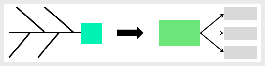
There are many tools that can be used to identify and present a cause-and-effect relationship using the fishbone diagram. One of the simplest and most straightforward ways is using this fishbone diagram template .
Wrapping Up
The fishbone diagram is a valuable tool for conducting cause-and-effect analyses. It offers a structured approach to identify and organize potential problem causes. This tool is considered one of the fundamental tools in Lean Six Sigma and other quality improvement methodologies. Combining the fishbone diagram with the “5 Whys” adds depth to the analysis and helps revealing the main causes and potential root causes. The outcome of a fishbone analysis provides useful information for later problem-solving tools.
Other Formats

Do you want to use the slides in your training courses?
Fishbone Diagram Training Material – $18.85
Related Articles
Why-Why Diagram

Interrelationship Map

Related Templates
Fishbone Diagram

Cause and Effect Matrix

Written by:
CIToolkit Content Team

Fishbone (Ishikawa) Diagram
Fishbone Diagrams (also known as Ishikawa Diagrams) are used in process improvement methods to identify all of the contributing root causes likely to be causing a problem.
Another name for this diagram is the "Cause & Effect" or CE diagram. A completed Fishbone diagram includes a central "spine" and several branches reminiscent of a fish skeleton.
Fishbone Diagrams can be used to answer the following questions that commonly arise in problem solving: What are the potential root causes of a problem? What category of process inputs represents the greatest source of variability in the process output?
Dr. Kaoru Ishikawa developed the "Fishbone Diagram" at the University of Tokyo in 1943. Hence the Fishbone Diagram is frequently referred to as an "Ishikawa Diagram." The Fishbone chart is an initial step in the screening process. After identifying potential root cause(s), further testing will be necessary to confirm the true root cause(s). This methodology can be used on any type of problem, and can be tailored by the user to fit the circumstances.
Using the Ishikawa approach to identifying the root cause(s) of a problem provides several benefits to process improvement teams:
- Constructing a Fishbone Diagram is straightforward and easy to learn.
- The Fishbone Diagram can incorporate metrics but is primarily a visual tool for organizing critical thinking.
- By Involving the workforce in problem resolution the preparation of the fishbone diagram provides an education to the whole team.
- Using the Ishikawa method to explore root causes and record them helps organize the discussion to stay focused on the current issues.
- It promotes "System Thinking" through visual linkages.
- It also helps prioritize further analysis and corrective actions.
How to Get Started
This tool is most effective when used in a team or group setting.
1. To create a Fishbone Diagram, you can use any of a variety of materials. In a group setting you can use a white board, butcher-block paper, or a flip chart to get started. You may also want to use "Post-It" notes to list possible causes but have the ability to re-arrange the notes as the diagram develops. There are also several software packages that can be useful in creating a Fishbone Diagram, including Microsoft Excel and EngineRoom . EngineRoom is available for a free trial so that you can practice making a Fishbone Diagram. Or you can watch the tutorial provided below that shows how to make and use a Fishbone Diagram using EngineRoom.
2. Write the problem to be solved (the EFFECT) as descriptively as possible on one side of the work space, then draw the "backbone of the fish", as shown below. The example we have chosen to illustrate is "Missed Free Throws" (an acquaintance of ours just lost an outdoor three-on-three basketball tournament due to missed free throws).

3. The next step is to decide how to categorize the causes. There are two basic methods: A) by function, or B) by process sequence. The most frequent approach is to categorize by function.
In manufacturing settings the categories are often: Machine, Method, Materials, Measurement, People, and Environment. In service settings, Machine and Method are often replaced by Policies (high level decision rules), and Procedures (specific tasks).
In this case, we will use the manufacturing functions as a starting point, less Measurement because there was no variability experienced from measurements (its easy to see if the ball goes through the basket).

4. You can see that this is not enough detail to identify specific root causes. There are usually many contributors to a problem, so an effective Fishbone Diagram will have many potential causes listed in categories and sub-categories. The detailed sub-categories can be generated from either or both of two sources:
- Brainstorming by group/team members based on prior experiences.
- Data collected from check sheets or other sources
A closely related Cause & Effect analytical tool is the "5-Why" approach, which states: "Discovery of the true root cause requires answering the question 'Why?' at least 5 times". See the 5-Why feature of the Toolbox. Additional root causes are added to the fishbone diagram below:

5. The usefulness of a Fishbone Diagram is dependent upon the level of development - moving past symptoms to the true root cause, and quantifying the relationship between the Primary Root Causes and the Effect. You can take the analysis to a deeper level by using Regression Analysis to quantify correlation, and Designed Experiments to quantify causation. As you identify the primary contributors, and hopefully quantify correlation, add that information to your chart, either directly or with foot notes.
The following chart has the top five primary root cause contributors highlighted in gold. The note "MC" (for Mathematical Correlation) attached to air pressure indicates that strong correlation has been established through statistical analysis of data (the lower the air pressure, the less bounce off the rim).
If you have ever tried to shoot baskets at a street fair or carnival to win a prize, you know that the operator always over-inflates the ball to lower your chances. Pick any system that works for you - you could circle instead of highlighting. The priority numbers can carry over to a corrective action matrix to help organize and track improvement actions.
6. The tutorial provided below that shows how to make and use a Fishbone Diagram using EngineRoom.
EngineRoom's Fishbone Diagram
Indented Hierarchy Fishbone
An alternate format for a Cause and Effect diagram is the "indented hierarchy fishbone". This format may be easier to use as it can be easily executed in a word processing or spreadsheet program. Following is an example of our Free-Throw example using the indented hierarchy method:
Effect - Made (Missed) Free Throws

Resources: Guide to Quality Control - Dr. Kaoru Ishikawa
Regardless, if one uses the graphical or the indented hierarchy Fishbone, this process improvement tool will greatly help understanding the significant factors involved in a process.
Creating this diagram with a cross functional team will build not only trust between departments but will cultivate new found knowledge and understanding for the key players in the process. When using the Fishbone as a discussion topic meetings can be better focused on process improvement and defect reduction.

See more tools
Check out additional tools in the Lean Six Sigma tool belt

Want to learn more?
MoreSteam.com offers a wide range of Lean Six Sigma online courses, including Black Belt, Green Belt, and DFSS training. Flexible training at an affordable price.
IMAGES
VIDEO
COMMENTS
A fishbone diagram is a problem-solving approach that uses a fish-shaped diagram to model possible root causes of problems and troubleshoot possible solutions. It is also called an Ishikawa diagram, after its creator, Kaoru Ishikawa, as well as a herringbone diagram or cause-and-effect diagram. Fishbone diagrams are often used in root cause ...
Also called: cause-and-effect diagram, Ishikawa diagram. This cause analysis tool is considered one of the seven basic quality tools. The fishbone diagram identifies many possible causes for an effect or problem. It can be used to structure a brainstorming session. It immediately sorts ideas into useful categories.
The Fishbone Diagram is a visual tool used in Lean Six Sigma to identify root causes of problems. It resembles a fish skeleton, with the main problem at the head and potential causes branching off the spine into categories, facilitating a systematic approach to problem-solving. Also commonly known as a Cause and Effect Diagram or an Ishikawa ...
The Fishbone Diagram, also known by various other names such as Ishikawa Diagram, Cause and Effect Diagram or 6Ms, is a visual tool used in problem-solving and root cause analysis.Originating from the quality management sector, it is used as a systematic approach to identify, explore, and display possible causes of a specific problem.
An example of the application of a fishbone diagram will be the typical 4S fishbone used in manufacturing. The 4S's represent - systems, surroundings, skills, and suppliers. Each 's' factor is accompanied by adjoint 'bones' which represent the issues in these attributes of the manufacturing process. Below is an example of a 4S ...
A fishbone diagram (also known as an Ishikawa fishbone diagram) is an effective problem-solving tool. Instead of focusing on a quick fix, creating a fishbone diagram helps to identify the root cause of a problem and find a long-term solution. As a type of cause and effect diagram, the "fishbone" name comes from the diagram's resemblance ...
A fishbone diagram, also referred to as a cause and effect diagram or an Ishikawa diagram, is a helpful tool for identifying the root cause of a problem.It allows you to list all the potential causes that may be contributing to the effect you are currently experiencing. This visual aid takes the shape of a fishbone, hence its name, and is commonly used during brainstorming sessions.
Here is a step-by-step guide on how to use the Fishbone Diagram: Clearly define the problem or issue you want to address. Draw a horizontal line and write the problem or issue at the end of the line. Identify the major categories or causes related to the problem and draw lines branching off from the central line.
A fishbone diagram, also known as an Ishikawa diagram or cause and effect diagram, is a tool used to identify the root causes of a problem. It is named after Japanese quality control expert Kaoru Ishikawa, who developed the concept in the 1960s. Organizations across a variety of industries, including manufacturing, healthcare, and service use ...
Ishikawa diagrams (also called fishbone diagrams, herringbone diagrams, cause-and-effect diagrams) are causal diagrams created by Kaoru Ishikawa that show the potential causes of a specific event.. Common uses of the Ishikawa diagram are product design and quality defect prevention to identify potential factors causing an overall effect. Each cause or reason for imperfection is a source of ...
Bone up on your fishbone diagrams with FigJam. Problem-solving is a team sport. Work together to zero in on root causes using FigJam's online collaborative whiteboard, then organize them with FigJam's ready-made fishbone diagram template. If you'd rather make one from scratch, use FigJam's free diagramming tools to:
4. Explore and start with a fishbone diagram template or create a new document in Lucidchart. Determine your problem statement. 5. The first thing you need for your fishbone diagram is a problem statement. Since fishbone diagrams are used to analyze cause-and-effect relationships, the problem statement is your final effect or result.
An easy to use tool for conducting a root cause analysis. What it is: The fishbone diagram Also referred to as "Ishikawa cause and effect" after Japanese founder and quality control expert Kaoru Ishikawa. is a tool to organize ideas and theories about what causes a problem or an event. How it works: Teams work together to brainstorm and identify potential causes and group them into several ...
A fishbone diagram, also known as cause and effect diagrams, Ishikawa diagram and Herringbone diagram, is a visualization tool used to find the root cause of a problem. It helps you group all the potential causes of a problem in a structured way to find the ultimate cause of your problem. Kaoru Ishikawa invented this diagram in the 1960s to use ...
A fishbone diagram is a visualization tool used in business to identify and investigate the many possible causes of a particular event, issue, or outcome. Fishbone diagrams are also known as cause and effect diagrams or Ishikawa diagrams, the latter named for the diagram's original creator, Japanese organizational theorist Kaoru Ishikawa.
Step 1 - Define the problem. The first step to solving any problem - and the key to learning how to make a fishbone diagram - is correctly defining it. A clearly defined problem makes it easier to identify causes. It also encourages us to determine whether there's even a problem to begin with. In this case, the problem we've ...
fishbone diagram: A fishbone diagram, also called a cause and effect diagram or Ishikawa diagram, is a visualization tool for categorizing the potential causes of a problem in order to identify its root causes.
Fishbone diagrams (also called Ishikawa diagrams and cause-and-effect diagrams) are visualizations used to identify and illustrate the causes for a specific event. Potential causes are often brainstormed and then categorized in order to identify a problem's root cause. The diagram gets its name due to the branches radiating out from the main ...
The fishbone diagram is a simple tool that allows quick and effective root causes to be understood, in the pursuit of corrective actions. Often referred to as a cause and effect diagram, or Ishikawa, it is a simple root cause analysis tool that is used for brainstorming issues and causes of particular problems and can and often is used in conjunction with the 5 Whys tool.
Step 1: Define the Problem. The first step in problem-solving, whether you use the Fishbone or not, is defining the problem correctly. Ideally, the problem statement will include an objective metric that can be used to determine success. For example, a problem statement such as, "The contact center abandon rate is too high," will not be as ...
A fishbone diagram, also known as an Ishikawa diagram or cause-and-effect diagram, is a visual tool used for problem-solving and root cause analysis. It's structured like a fish skeleton, with the problem at the "head" and potential causes branching off as "bones.". These branches represent different categories, such as People ...
The Ishikawa fishbone diagram or just fishbone diagram, named after its creator Kaoru Ishikawa, is a powerful visualization tool designed to map out causal relationships concerning a particular problem or issue. Its unique design, reminiscent of a fish's skeletal structure, places the primary problem or effect at the fish's head.
Named for its fish-like appearance, the Fishbone diagram is a problem-solving technique designed to help arrive at the root cause of an issue. Using a Fishbone project management diagram, you can analyze even the most complex projects and isolate any factors that contributed to process breakdowns. Think of it this way.
Fishbone analysis is a collaborative exercise, fostering the capture, categorization, and organization of the collective knowledge held by a team regarding a problem or process. By going through the steps of drawing the diagram with your team, everyone gains insight into the cause-and-effect, which makes the solution easier to find.
Fishbone Diagrams (also known as Ishikawa Diagrams) are used in process improvement methods to identify all of the contributing root causes likely to be causing a problem. Another name for this diagram is the "Cause & Effect" or CE diagram. A completed Fishbone diagram includes a central "spine" and several branches reminiscent of a fish ...
Five steps to creating a fishbone diagram 1. Create a problem statement and write it at the "head" of the fish. This is the "effect." 2. Define the categories of possible causes and write them at the end of each rib. ... Use the "5 Whys" process to analyze the most important causes further. Add additional "bones" to the fish to record these. 5 ...