- 4 Best Project Management Certifications for Beginners with Top Salary
- 2024 PMP Exam and PMP Certification-What You Must Know
- PMP Certification Success Roadmap in 9 Steps
- PMP Certification Cost – The Complete Guide
- Is PMP Worth It, PMP Salary, and 10 PMP Certification Benefits
- CAPM vs PMP: Which Certification Is Right For You?
- PMP vs PRINCE2 Certification – What’s the Difference?
- How to Fill in Your PMP Application (Examples, Tips, Steps)

Complete Guide for PMP Project Description
- PMP Project Description Reference Sheet
- PMP Audit Preparation
- How to complete PMP Application without project manager job title
- PMP Project vs Operation Demystify
- Process Group and Knowledge Area Mapping Game
- PMP Flashcards
- PMP ITTO Review
- PMP ITTO Game
- Org Structure Game
- Top 9 PMP Study Tips to Ace PMP Exam in 2024
- PMP Online Proctored Exam Definitive Guide: Tips, Checklist, and More
- 5 TIPS for Surviving PMP Exam at Pearson VUE Testing Center
- PMP Formulas Cheat Sheet
- Must-Know for PMP Exam Change in 2020/2021
- Project Charter vs Project Plan (Example, Template)
- What Is WBS?
PERT Chart vs Gantt Chart: Pros, Cons, Comparison, Examples
What is a risk register: example, free template & tips, what is an affinity diagram: example, tips for creating one.
- Complete PMP Resources & Free Exam Questions
- Best PMP Boot Camp Online Reviews
- Best PMP Exam Simulators
- Best PMP Study Guide Reviews and PMP Exam Prep Books
- PM-Prepcast Review
PM Prepcast Coupon Code [March 2024]
- Project Management Academy Review & Coupon
- Velociteach Review & Coupon
- PMTraining Review
- Edureka Review
- Master of Project Academy Review
- KnowledgeHut PMP Review
- Simplilearn Review
- About PMAspirant
- How You Can Help
- Helping PMP candidates with application and exam
Cause and Effect Diagram (Fishbone, Ishikawa): Ultimate Guide with Examples

Last Updated on January 8, 2024 by andrewshih
The Cause and Effect Diagram, also known as the Fishbone or Ishikawa Diagram, is a useful visual tool that aids in identifying and understanding the root causes of a problem.
In this comprehensive guide, we will explore the intricacies of the Cause and Effect Diagram, providing a step-by-step procedure, a practical example, and resources for implementation.
What Is Cause And Effect Diagram
Cause and Effect Diagram is a graphical representation that illustrates the cause-and-effect relationships within a system or a specific problem.
Developed by Kaoru Ishikawa, this diagram is widely used in various industries to analyze complex issues and facilitate effective problem-solving.
The diagram gets its name from its fishbone-like structure, where the problem statement is placed at the “head,” and various potential causes branch out like the “bones” of the fish.
The primary purpose of an Ishikawa Diagram is to provide a comprehensive and structured method for identifying, categorizing, and analyzing the factors that contribute to a specific problem.
By visually organizing potential causes into distinct categories, the diagram helps teams and individuals gain a clearer understanding of the relationships between different elements of a system, process, or situation.

When To Use A Fishbone Diagram
Here are some instances when using a Fishbone Diagram is particularly beneficial:
Complex Problem Solving
When faced with a complex problem that involves multiple factors and potential causes, a Fishbone Diagram can help break down the complexity into manageable categories. It provides a structured approach to understanding the interrelationships among different elements contributing to the issue.
Quality Improvement
In industries that prioritize quality control, such as manufacturing or healthcare, a Fishbone Diagram is often used to investigate defects, errors, or deviations from standards. It helps teams explore and address the underlying causes affecting product or service quality.
Process Improvement
When analyzing and improving business processes, a Fishbone Diagram can be instrumental in identifying bottlenecks, inefficiencies, or breakdowns in the workflow. By categorizing potential causes, teams can streamline processes for increased efficiency.
Project Planning
During the planning phase of a project, a Fishbone Diagram can be used to anticipate potential challenges and risks. It aids in proactive problem identification and mitigation strategies, contributing to more successful project outcomes.
Team Collaboration
When teams are working on a shared goal or project, a Fishbone Diagram encourages collaborative brainstorming sessions. It provides a visual platform for team members to contribute their insights and perspectives, fostering a collective understanding of the problem.
Customer Complaints
In customer-centric industries, a Fishbone Diagram can be deployed to investigate and address customer complaints. It helps identify the underlying causes of dissatisfaction and guides the development of strategies to enhance customer satisfaction.
Training and Development
In educational settings or corporate training programs, a Fishbone Diagram can be utilized to analyze challenges or obstacles hindering effective learning and development. It assists in identifying areas for improvement in training processes.
Strengths of Cause and Effect Diagrams
Visual representation.
One of the main strengths of cause and effect diagrams is their ability to provide a visual representation of complex issues. The diagram’s fishbone structure allows for a clear and organized display of potential causes and their relationships, making it easier for teams to understand and communicate.
Systematic Analysis
Cause and effect diagrams promote a systematic approach to problem-solving. By categorizing potential causes into major branches, teams can methodically explore and analyze each factor, leading to a comprehensive understanding of the root causes of a problem.
Collaborative Problem Solving
The creation of a cause and effect diagram often involves collaborative brainstorming sessions. This encourages team members to share their insights and perspectives, fostering a collaborative problem-solving environment that capitalizes on collective knowledge and expertise.
Identification of Multiple Causes
The diagram facilitates the identification of multiple causes contributing to a single problem. This multiperspective analysis helps ensure that the root causes are thoroughly explored, reducing the likelihood of overlooking critical factors.
Weaknesses of Cause and Effect Diagrams
Oversimplification.
One weakness of cause and effect diagrams is the potential for oversimplification. The structured nature of the diagram may not capture the complexity or interdependencies of certain issues, leading to a superficial understanding of the problem.
Subjectivity in Prioritization
The prioritization of causes within the diagram can be subjective. Teams may struggle to objectively rank the importance of various factors, and the process may be influenced by individual perspectives, biases, or incomplete information.
Lack of Quantitative Data
Cause and effect diagrams are primarily qualitative tools and do not inherently incorporate quantitative data. While they are effective in identifying potential causes, they may not provide a precise measurement of the impact or significance of each cause, requiring supplementary quantitative analysis.
How to Create Fishbone Diagram Step-by-Step
Creating a Cause and Effect Diagram involves systemically identifying and categorizing potential causes of a specific problem. Here are the steps to create a cause-and-effect diagram:
Step 1: Define the Problem Statement

Clearly articulate the problem or issue that you want to address. Write it as a concise statement at the “head” of the Fishbone Diagram.
Step 2: Identify Major Categories (Fishbone Bones)
The next step is to create the main branches, or “bones,” of the fishbone diagram.

Teams using cause-effect diagrams often use additional mnemonic lists to ensure a thorough consideration of potential causes. For example, the manufacturing industry frequently utilizes 5Ms, and the service industry often uses 5Ps.
While these lists serve as helpful aids, they are not universally applicable, and individuals may create their own or modify existing ones. The key is to consider all potential sources of causation by asking targeted questions like, “What procedures might be causing this problem?”
Step 3: Brainstorm Causes Within Each Category
With your team, brainstorm potential causes within each category.

Encourage open discussion and gather as many ideas as possible. There are several techniques that may be helpful during the storming process.
- Use Affinity Diagrams to organize the information and group related ideas.
- Utilize 5 Whys Analysis to repeatedly ask why for a thorough cause and effect chain analysis.
- Ask the 4 Ws – What, Why, When, and Where to help explore the cause and effect.
Step 4: Add Subcauses and Details
If necessary, the team can further expand on each identified cause by adding subcauses or specific details. This adds granularity to the diagram, making it more comprehensive.

Using the image above, the team has identified two sub-causes for the main cause #1.
Continue this process until the team feels that the causes and sub-causes are sufficiently detailed. The team can continue to add additional sub-levels to sub-causes if necessary, although the diagram can become more difficult to visualize with multiple levels.
Step 5: Prioritize Causes
If applicable, prioritize the causes based on their significance. This can be done through team discussion, voting, or using data such as the Pareto Principle to identify the most critical factors.
Step 6: Review, Validate, and implement
Review the completed Fishbone Diagram with the team. Ensure that all relevant causes have been included and that the relationships between causes and effects are accurate. Finally, share the completed diagram with relevant stakeholders and use it as a visual aid to identify and solve the problem.
By following these steps, the team can utilize the Fishbone Diagram to systematically analyze complex problems, identify root causes, and drive effective solutions.
Tips for Creating a Cause and Effect Diagram
Here are some tips to enhance the process and maximize the value of the fishbone diagram:
Tips for Creating the Diagram
- Clearly Define the Problem : A well-defined problem statement ensures that the cause-and-effect analysis remains focused and relevant.
- Select Appropriate Categories : Tailor these categories to fit the specific context of your analysis.
- Use Facilitation Techniques : Employ facilitation techniques such as affinity diagrams to organize and group related causes. Or use the 5 Whys technique to dig deeper into the root causes of each identified issue.
- Keep it Visual and Simple : Maintain clarity and simplicity in the Fishbone Diagram. Use clear and concise language, and avoid overcrowding the diagram with excessive detail. Make the diagram easy to understand and communicate.
Tips for Collaboration
- Encourage Open Brainstorming : Encourage team members to share their insights and ideas freely. Avoid judgment during the initial brainstorming phase to stimulate creativity.
- Include Relevant Stakeholders : Involve stakeholders with diverse perspectives in the cause-and-effect analysis to capture a comprehensive view of the problem and its contributing factors.
- Review and Iterate : After creating the initial diagram, review it with the team to confirm its accuracy and completeness. Be open to feedback and make necessary adjustments and several iterations.
- Facilitate Follow-Up Action : Use the insights gained from the Fishbone Diagram to develop actionable plans and solutions. Assign responsibilities for implementing changes and track progress over time to ensure continuous improvement.
By following these tips, you can facilitate a more effective cause-and-effect analysis, leading to a Fishbone Diagram that serves as a valuable tool for problem-solving and decision-making.
Cause and Effect Diagram Examples
Here are three examples of Ishikawa Diagrams representing different scenarios:
Example 1: Production Delays in a Manufacturing Plant
In this scenario, you are tasked with identifying the various factors contributing to production delays, allowing the team to identify root causes and implement targeted solutions.
Problem Statement : Unexpected delays in the production process lead to reduced output.
From the brainstorming exercise, the team identified the following causes within each category:
- Manpower : Insufficient Training, Staff Shortage, Lack of Motivation
- Machinery : Equipment Malfunctions, Inadequate Maintenance, Outdated Technology
- Material : Defective Raw Materials, Supply Chain Issues, Inventory Management
- Methods : Inefficient Workflows, Lack of Standard Operating Procedures, Poor Planning
- Measurement : Inaccurate Performance Metrics, Lack of Key Performance Indicators (KPIs), Monitoring and Reporting Issues

Example 2: High Employee Turnover in a Company
In this scenario, you are tasked with identifying the root causes of high employee turnover and guiding the development of strategies to improve retention.
Problem Statement : High turnover rates lead to instability and decreased morale among employees.
- People : Poor Leadership, Lack of Recognition, Limited Growth Opportunities
- Processes : Inefficient Recruitment, Inadequate Onboarding, Poor Performance Management
- Policies : Lack of Work-Life Balance, Inflexible Policies, Unclear Communication
- Work Environment : Toxic Culture, Inadequate Facilities, Lack of Team Collaboration
- Compensation & Benefits : Below-market Salaries, Inadequate Benefits, Limited Incentives
While taking a deep dive and examining the potential causes of insufficient recruitment, the team identified poor job descriptions, limited recruitment channels, and a competitive job market.

Example 3: Customer Complaints in a Service Industry
In this scenario, you are tasked with understanding the causes of multifaceted customer complaints and helping the organization to enhance its service quality and address customer concerns effectively.
Problem Statement : Increasing customer complaints leads to a decline in customer satisfaction.
- People : Inadequate Training, Lack of Empathy, Communication Issues
- Process : Inefficient Service Delivery, Long Waiting Times, Lack of Quality Control
- Product : Defective Products, Inadequate Product Information, Poor Product Design
- Policies : Inconsistent Policies, Lack of Customer-Focused Policies, Misleading Information
- Environment : Unpleasant Atmosphere, Poor Customer Service Culture, Lack of Feedback Mechanism
While taking a deeper dive into the long waiting time, the team identified insufficient staffing, and technical malfunctions as potential causes.
As the team continued to look into the cause of insufficient staffing, the team identified budget constraints, poor scheduling, and unexpected sickness as the causes.

Cause And Effect Diagram Complimentary Techniques
While the Fishbone Diagram (Ishikawa Diagram) is the most well-known type of Cause and Effect Diagram, there are other variations and complementary techniques used for cause and effect analysis. Here are some notable ones:
Affinity Diagram
An affinity diagram serves as the starting point by organizing diverse ideas and grouping them into clusters. It acts as a foundation for the fishbone diagram, which then delves into a more detailed analysis of root causes within specific categories.
Together, these tools provide a comprehensive approach to problem-solving, transitioning from idea generation and organization to in-depth cause-and-effect analysis.
5 Whys Analysis
Although not a diagram per se, the 5 Whys is a questioning technique that helps delve deeper into the root cause of a problem. It involves asking “Why?” repeatedly (typically five times) to trace the cause-and-effect chain until the fundamental issue is uncovered. The 5 Whys Analysis is often used in conjunction with Fishbone Diagrams for a more thorough investigation.
Pareto Chart
A Pareto Chart is often used in conjunction with Fishbone Diagrams. It helps prioritize issues by illustrating the relative importance of different causes. The Pareto Principle suggests that 80% of problems may be attributed to 20% of the causes, guiding teams to focus on the most significant contributors.
How do I prioritize causes in a Fishbone Diagram?
Causes can be prioritized based on their significance or impact. This can be done through team discussion, voting, or using data such as the Pareto Principle to identify the most critical factors that require immediate attention.
Can I use a Fishbone Diagram for project planning?
Yes, a Fishbone Diagram can be a useful tool in the planning phase of a project. It helps anticipate potential challenges, risks, and issues, allowing teams to develop proactive strategies for successful project outcomes.
How often should I revisit a Fishbone Diagram?
Revisit a Fishbone Diagram as needed, especially when there are changes in the problem, new information becomes available, or when monitoring progress on implemented solutions. It’s a dynamic tool that can be iteratively improved over time.
What is the difference between an affinity diagram and a fishbone diagram?
An affinity diagram is used for brainstorming and organizing ideas, providing a foundation for a Fishbone Diagram. The Fishbone Diagram then conducts a more detailed analysis of root causes within specific categories identified by the affinity diagram. They work together in a collaborative problem-solving process.
What are the 6 elements of a Fishbone Diagram?
The Fishbone Diagram typically consists of six major elements or “bones.” These elements represent different categories under which potential causes of a problem are grouped. The six categories are People, Processes, Equipment, Materials, Environment, and Management . Each category helps organize and analyze potential causes systematically, providing a comprehensive view of the factors contributing to a specific issue.
RELATED ARTICLES MORE FROM AUTHOR

POPULAR POSTS

2024 Complete PMP Resources with Free PMP Exam Questions

POPULAR CATEGORY
- Resources 17
- Application 6
- Privacy Policy
- Terms and Conditions
- Affiliate Disclaimer

- Guide: Fishbone Diagram
Daniel Croft
Daniel Croft is an experienced continuous improvement manager with a Lean Six Sigma Black Belt and a Bachelor's degree in Business Management. With more than ten years of experience applying his skills across various industries, Daniel specializes in optimizing processes and improving efficiency. His approach combines practical experience with a deep understanding of business fundamentals to drive meaningful change.
- Last Updated: October 19, 2023
- Learn Lean Sigma
The Fishbone Diagram, also known by various other names such as Ishikawa Diagram, Cause and Effect Diagram or 6Ms, is a visual tool used in problem-solving and root cause analysis . Originating from the quality management sector, it is used as a systematic approach to identify, explore, and display possible causes of a specific problem.
Table of Contents
What is a fishbone diagram.
The Fishbone Diagram is a graphical tool used for identifying and organizing possible causes of a specific problem or outcome. The diagram resembles the skeletal structure of a fish, hence its name. At the “head” of the fish is the problem you’re trying to solve, and the “bones” branching off the spine are the multiple potential causes contributing to that problem.
The benefit of a Fishbone Diagram lies in its simplicity. It gives you a structured way to brainstorm and categorize the various factors affecting a specific issue. The diagram can get as detailed as you need it to be, allowing for sub-causes to branch off the main causes, offering even deeper insights.
The Components of a Fishbone Diagram
Head : The fish’s head represents the problem or effect you’re analyzing.
Spine : The long, horizontal line connecting to the head serves as the timeline or sequence of the problem.
Bones : These are the categories of potential causes. They branch off the spine, leading towards the head.
Sub-Bones : These are the more specific factors or sub-causes that stem from the main categories.
Why Use a Fishbone Diagram?
The Fishbone Diagram is a flexible tool that can be used for a range of applications. Here’s why it’s so useful:
1. Easy Visualization:
One of the primary advantages of using a Fishbone Diagram is its ability to simplify complex problems. With all potential causes visually represented in one place, it becomes easier to analyze and discuss the issues.
2. Team Collaboration:
The Fishbone Diagram is excellent for brainstorming sessions. It encourages team members to think critically and contributes to a shared understanding of the problem. It’s collaborative by design, allowing for the collective intelligence of the group to shine.
3. Root Cause Analysis:
Identifying symptoms of a problem is one thing; uncovering the root cause is another. The Fishbone Diagram excels at this by forcing you to dig deep into various contributing factors. By isolating these causes, you’re better positioned to find a lasting solution.
By using a Fishbone Diagram, you’re not just addressing a problem with a short-term fix; you’re conducting a thorough investigation to eliminate issues from the root up.
How to Create a Fishbone Diagram: A Detailed Guide
Creating a Fishbone Diagram might seem like a daunting task, but it’s actually a straightforward process. Here, we’ll break down each step in detail to ensure you can construct a Fishbone Diagram that serves its purpose effectively.
Materials You’ll Need:
- A whiteboard or large sheet of paper
- Markers or pens
- Sticky notes (optional)
- A team of people for brainstorming
Step 1: Identify the Problem
The first and most crucial step is to clearly identify the problem you’re trying to solve. This statement should be specific and concise. Write this problem statement at the far right side of your whiteboard or paper, as it will serve as the “head” of your fishbone diagram.
- Use data to define the problem whenever possible.
- Make sure the problem is mutually understood and agreed upon by all team members.
Step 2: Determine the Main Categories
Now, draw a horizontal line from the problem statement towards the left side of the board. This is the “spine” of your fish. Next, you’ll identify the major categories of causes that could be contributing to the problem. These categories will serve as the main “bones” branching off from the spine.
Common categories often include:
- Measurement
- Environment
- The categories can be industry-specific or general, depending on the problem you’re analyzing.
- Aim for 4-6 main categories for better manageability.
Step 3: Brainstorm Causes
Once you’ve determined the main categories, it’s time to brainstorm potential causes for each category. These causes will be the smaller “bones” that branch off from the main bones. If you’re working with a team, this is an excellent time for a brainstorming session.
- Use sticky notes to write down ideas so you can easily move them around.
- Encourage every team member to contribute; sometimes the most unexpected insights come from diverse perspectives.
The output of the root cause analysis at this point may look something like the below example. With the lack of preventative maintenance being explored with the 5Whys analysis.
Step 4: Dig Deeper with Sub-Causes
Sometimes, the primary causes can be broken down into smaller, more specific sub-causes. This is where the “ 5 Whys ” technique can be beneficial. For each primary cause, ask “Why?” up to five times to dig deeper into the root of the issue.
- Not all primary causes will need sub-causes; use your discretion.
- Keep the diagram organized to ensure readability.
Step 5: Analyze and Take Action
After all the causes and sub-causes have been identified, it’s time to analyze the Fishbone Diagram as a team. Highlight or circle the causes that seem most likely to be contributing to the problem. These are the areas that will need immediate attention and action.
- Use data or evidence to support your conclusions.
- Create an action plan assigning responsibility for each highlighted cause.
And there you have it! You’ve successfully created a Fishbone Diagram that will help you get to the root of your problem.
Examples and Case Studies: Understanding Fishbone Diagrams in Action
Case study: manufacturing unit with quality issues.
Imagine you run a manufacturing unit, and you’ve been receiving complaints about the quality of your products. You decide to use a Fishbone Diagram to get to the root of the issue.
Step 1: Identify the Problem Problem Statement: “High number of defective products in the last quarter.”
Step 2: main categories.
- People : Untrained staff, high employee turnover
- Process : Inconsistent quality checks, outdated SOPs (Standard Operating Procedures)
- Equipment : Aged machinery, lack of maintenance
- Environment : Poor lighting, extreme temperature fluctuations
Step 4: Dig Deeper (5 Whys)
- Untrained Staff : Why? No formal training program.
- Aged Machinery : Why? No budget allocated for equipment upgrades.
After analyzing the Fishbone Diagram, you realize that untrained staff and aged machinery are your primary culprits. Your next steps could involve investing in staff training programs and allocating budget for machinery upgrades.
By following these steps, you can develop targeted strategies to improve product quality significantly.
Common Mistakes and Tips: How to Make the Most of Your Fishbone Diagram
1. overlooking minor causes.
While it’s easy to focus on the most glaring issues, minor causes can accumulate and have a significant impact.
Tip : Don’t disregard a cause just because it seems minor. Sometimes, fixing smaller issues can lead to big improvements.
2. Ignoring Data
It’s tempting to rely solely on brainstorming and intuition, but data should be your guiding star.
Tip : Use metrics and KPIs to support or refute the causes you’ve identified. This adds credibility to your findings and helps you prioritize effectively.
3. Stopping at Symptoms
Identifying symptoms is just the first step; your ultimate goal should be to uncover the root causes.
Tip : Use techniques like the “5 Whys” to dig deeper into each cause and ensure you’re addressing the root of the issue, not just its manifestations.
Fishbone Diagrams are a fantastic asset in the toolbox of anyone interested in continuous improvement. Whether you’re a seasoned professional or just getting started, this simple yet powerful tool can help you dissect complex problems and develop targeted solutions.
They encourage you to look beyond the obvious and delve into the intricacies that contribute to each problem. So go ahead, grab that pen and paper (or a whiteboard, if you’re feeling fancy), and start your journey towards effective problem-solving.
- Ilie, G. and Ciocoiu, C.N., 2010. Application of fishbone diagram to determine the risk of an event with multiple causes. Management research and practice , 2 (1), pp.1-20.
- Coccia, M., 2018. The Fishbone diagram to identify, systematize and analyze the sources of general purpose Technologies. Journal of Social and Administrative Sciences , 4 (4), pp.291-303.
Q: What is the origin of the Fishbone Diagram?
A: The Fishbone Diagram was originally developed by Dr. Kaoru Ishikawa, a Japanese quality control statistician, in the 1960s. It’s also sometimes referred to as the Ishikawa Diagram in his honor.
Q: Can Fishbone Diagrams be used for non-manufacturing problems?
A: Absolutely! While Fishbone Diagrams are popular in manufacturing and quality management, their application is not limited to these areas. They can be used in healthcare, software development, event planning, and even for personal problem-solving.
Q: How many main categories should my Fishbone Diagram have?
A: The number of main categories can vary depending on the complexity of the problem. However, it’s generally advisable to have between 4-6 main categories for easier analysis and readability.
Q: Can I use software to create a Fishbone Diagram?
A: Yes, there are several software tools available for creating Fishbone Diagrams, such as Microsoft Visio, Lucidchart, and various other project management software options. However, a simple pen and paper or a whiteboard can be just as effective for smaller teams or simpler problems.
Q: How do I know which causes to prioritize after creating a Fishbone Diagram?
A: After creating your Fishbone Diagram, you should analyze it with your team to identify the most likely root causes of the problem. Using data to support your conclusions can be very helpful. You may also employ techniques like the Pareto Analysis to prioritize causes based on their impact.
Daniel Croft is a seasoned continuous improvement manager with a Black Belt in Lean Six Sigma. With over 10 years of real-world application experience across diverse sectors, Daniel has a passion for optimizing processes and fostering a culture of efficiency. He's not just a practitioner but also an avid learner, constantly seeking to expand his knowledge. Outside of his professional life, Daniel has a keen Investing, statistics and knowledge-sharing, which led him to create the website learnleansigma.com, a platform dedicated to Lean Six Sigma and process improvement insights.
Free Lean Six Sigma Templates
Improve your Lean Six Sigma projects with our free templates. They're designed to make implementation and management easier, helping you achieve better results.
Other Guides
How to build a fishbone diagram and get the most out of it

No business operates without problems along the way. But to solve them in time, you’ll need to be able to determine the cause quickly. That’s where using a fishbone diagram comes in.
A fishbone diagram , also known as the Ishikawa diagram or cause-and-effect diagram, is a tool you can use to visualize all of a problem’s potential causes, allowing you to discover the root causes and identify the best possible solution.
We put this guide together to show you how to make a fishbone diagram based on a fictional problem we’ll be investigating: why a software company’s customer churn is so high.
Let’s get started.

Step 1 – Define the problem
The first step to solving any problem – and the key to learning how to make a fishbone diagram – is correctly defining it. A clearly defined problem makes it easier to identify causes. It also encourages us to determine whether there’s even a problem to begin with.
In this case, the problem we’ve identified is that 40% of users cancel their subscriptions after the first month — which keeps us from reaching our goal of keeping cancellations below 20%. Now that we’ve identified our main problem, we can go ahead and add that to the fishbone diagram.

Problem definition tips:
- If you’re using the fishbone diagram to design a process or increase productivity, it’s just as important to correctly define your output. Your goals should be objective and achievable.
- Place the problem (the fish head) on one side of the diagram, and build the rest of the diagram (the fish bones) out to its left or right. The idea is that the “fish bones” indicate the impact of the causes.
- Place the causes with the biggest impact closer to the fish head and the causes with the smaller impact further away.
Step 2 – Decide on key categories of causes
Next, decide what areas of the problem are key to determining the actual cause. Going back to our example of investigating a high churn rate, here are three areas worth looking into:
- Subscription system
Once you start considering potential causes, you might find that most of them fall within one of these three categories. But you can always add more categories if needed. For example, If you think marketing impacted your retention figures, you could add that as a fourth area.
You can have as many areas as you need to. But to keep things simple, we recommend limiting yourself to no more than 10 — especially since we’re only learning how to make a fishbone diagram with this example.

Step 3 – Determine the actual causes of the problem
Now that you’ve defined the key areas to look into, let’s go through each one to determine all the individual influences that can affect our output. Look at each category and list every possible cause you can think of.
Looking at the subscription system, some possible causes include:
- We aren’t offering enough payment options
- The payment and registration systems are difficult to navigate
- Credit cards expire, voiding renewal
- The system doesn’t send out reminders for renewals.
When considering the user, potential causes include:
- Users don’t understand the full benefit of the software
- Users don’t know how to use all the functions
- Users experience delays when contacting support
- Users don’t use the software continuously, only requiring it for a few days at a time
- Users forget about the product.
When it comes to the software itself, potential causes may be:
- The software is unstable and crashes regularly
- The software is difficult to use
- Software installation requires multiple plugins to function well
- Key functionality requires additional subscriptions
- The software is insecure.
These are just a few potential causes. You should fill your fishbone diagram with as many different causes as you can come up with. Note that not every area of your diagram needs to have causes. Some might even have more causes than others.
Regardless, you now have a starting point to determine root causes. To keep going, investigate each cause to establish its actual effect on your output.

Tips to determine the actual cause:
- Run a brainstorming session or lay out a process map to generate better causes for your fishbone diagram
- Invite other team members in the process to make sure you’ve identified all the potential causes
- Some causes may have multiple sub-causes. Expand your fishbone diagram as needed to encompass all possible causes.
Step 4 – Using tools to plan the way forward
Remember, a fishbone diagram helps identify a problem’s causes. It doesn’t lead to solutions on its own. In fact, part of learning how to make a fishbone diagram is knowing what other tools you can use to identify causes more effectively.
Here are a few more tools to help you take your fishbone diagram to the next level:
Process Map
A process map is a flowchart of a specific system, showing all its inputs and outputs. It works best in areas like the manufacturing industry, where each product has a clearly defined process with multiple steps.
Process mapping involves looking at each step of the process one by one and listing all the potential influences. In an actual manufacturing environment, this may include being present on the production line and viewing the system, taking notes as you go through the process.
A process map is very effective at making sure you consider all the steps and influences involved in a system. In other words, it helps you clearly identify potential causes and add them to your fishbone diagram.
Brainstorming
Brainstorming is a fairly common tool in modern businesses. Instead of considering all the factors of a fishbone diagram by yourself, include others in the process. When working alone, it’s easy to overlook certain areas and completely miss others.
That’s why it’s worth making sure your brainstorming session takes the shape of a clearly-defined meeting. Have someone lead the session, taking note of any ideas team members offer up and leaving room for discussion. The goal is to end the brainstorming session with a list of causes to add to your fishbone diagram.
Once you’ve filled out your fishbone diagram, make sure everyone’s on the same page about how to follow up — whether it’s about delegating tasks or setting clear deadlines.
Tips for planning next steps:
- Not sure what causes to investigate? Collaborate with your team members on developing a cause-and-effect matrix. This way, you’ll get to rank causes by priority based on your team’s experience.
- Want to address a problem’s root cause and not just its symptom? Use our 5 Whys Template to take a closer look.
- How to make a fishbone diagram in a remote team
A fishbone diagram is more effective when multiple people get involved in creating it. But if your team works in remote and hybrid settings, you’ll need a tool designed to facilitate seamless collaboration.
Miro’s visual workspace is built for collaboration, making it easy to make a fishbone diagram together in real time — even if you aren’t in the same room. Seamlessly build diagrams using our intuitive, automated diagramming tools and our drag-and-drop, infinite canvas.
Not sure how to make a fishbone diagram from scratch? Save time using our free Fishbone Diagram Template . It’s fully customizable, allowing your team to add as much detail as you want and adjust its look and feel.
Tips for collaborating on a fishbone diagram in Miro:
- Invite your team to edit your board with you in real-time
- Invite stakeholders to view and comment on your Miro board for instant feedback
- Differentiate ideas by color-coding them
- Use frames to present your fishbone diagram and easily export it as a PDF or image
- Use sticky notes to add important context when building your fishbone diagram
Above all, avoid trying to build your fishbone diagram too quickly. Take the time to understand all the contributing factors, and make sure that anything you add to the fishbone diagram adds value.
- When to use a fishbone diagram?
Though fishbone diagrams were originally meant for problem-solving, they’re far more versatile — helping you break down any process or system into its contributing factors.
Here are a few use cases where knowing how to make a fishbone diagram comes in handy:
- To analyze a problem statement
- To brainstorm the causes of the problem (root cause analysis)
- To analyze a new design
- Process improvement
- Quality improvement
When in doubt, talk to your team to clarify the problem you’re investigating and how a fishbone diagram would help.
Miro is your team's visual platform to connect, collaborate, and create — together.
Join millions of users that collaborate from all over the planet using Miro.
- Step 1 – Define the problem
- Step 2 – Decide on key categories of causes
- Step 3 – Determine the actual causes of the problem
- Step 4 – Using tools to plan the way forward
Keep reading
Agile beyond software development: how to empower non-tech teams.

Don’t let ideas die post-retro: 5 ways to make retrospectives more actionable

Removing the hassle of brainstorm documentation with Miro + Naer

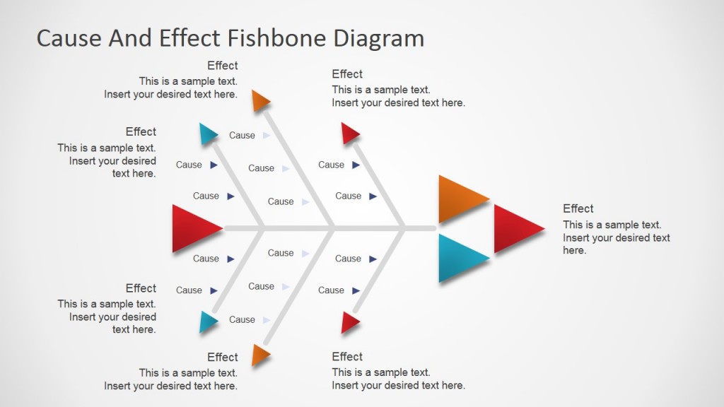
Home Blog Business Fishbone Diagram: Cause and Effect Analysis (Examples & Templates Included)
Fishbone Diagram: Cause and Effect Analysis (Examples & Templates Included)

Identifying the relationship between events and things is required when solving a problem, where possible causes are inspected to know their effect in an effort to generate the possible causes of a problem and minimize them.
For this purpose, a visualization tool called the fishbone diagram is used to list all of the possible causes and effects of the problem at hand, sorting them into categories, identifying root causes, and finding their solutions.
In this article, we will explain what is a fishbone diagram for problem-solving, when to use it, the elements of a fishbone analysis, how to make a fishbone diagram, and a fishbone diagram examples.
Lastly, we will also discuss how a fishbone diagram, specifically a cause and effect fishbone diagram, can be presented, with bonus templates that can be used to construct a fishbone diagram to determine causes and effects and come up with a solution to the problem.
Table of Contents
What is a Fishbone Diagram?
When to use a fishbone diagram, elements of the fishbone diagram, how to construct a fishbone diagram for cause and effect analysis, alternative to fishbone diagram, examples of fishbone diagram, pros of fishbone diagrams, cons of fishbone diagrams, how to present a fishbone analysis, templates for presenting a fishbone diagram.
A fishbone diagram is a visualization tool, developed by Dr. Kaoru Ishikawa, a quality control specialist, for identifying the root causes of a problem, categorizing them, and generating solutions.
Also called the Ishikawa diagram, or cause and effect diagram, the fishbone analysis is often used in troubleshooting and product development processes where teams need to focus on a problem statement.
The fishbone diagram has categories with branches that detail the causes of the problem; it looks like the skeleton of a fish, hence the name “Fishbone.” Each bone of the fish branches out into smaller bones to address the root causes of a large problem.

A fishbone diagram is used to conduct a cause-and-effect analysis. It enables teams to identify potential and real causes that are further investigated to determine the root cause. It can be used when,
- Managers need to identify the root cause of a problem
- Supervisors try to understand the contributing factors of any system or process failure
- Collaborative team brainstorming is required for problem-solving
- Streamlining an existing workflow by uncovering bottlenecks
- Improve output quality and efficiency

Manpower: Human Resources
Anything related to people that are involved with the process relevant to the problem statement. Manpower commonly includes operators, employees, maintenance teams, supervisors, and quality control specialists.
Machine: Facilities and Equipment
This includes machines used in the process, including all facilities and equipment that may be causing the problem. The causes can be associated with maintenance, usage, and assembly of equipment that could result in bottlenecks.
Method: Processes
Any standardized methods set by supervisors might not be followed by operators accurately. The instructions need to be evaluated to ensure all processes are clear to the team and all areas of operation are described in detail.
Material: Supplies and Resources
All supplies and resources used in the production or process are reviewed to determine their effect. Material defects, mishandling, low quality, and lack of proper inspection can result in problems further along the process.
Measurement: Quality Control
Techniques and tools used to measure quality standards are also a part of the fishbone analysis. Parts and processes need to be analyzed to determine whether they meet the quality control standards set in place, and all problems need to be reviewed to determine the root cause of the problem.
Mother Nature: Environment
When searching for a root cause, the environment plays a crucial role in production processes, whether it is the external factors of the production area or the environmental conditions such as temperature, humidity, pressure, etc. The production facilities must be able to handle the environment without having any negative impact on the production or process for a streamlined workflow.

Draft a Clear Problem Statement
For constructing a fishbone diagram, a clear problem statement needs to be drafted to test causes in order to determine what’s causing the problem and present a solution.
During analysis, the problem statement is written at the right side of the fishbone, at the head of the fish. The problem is the effect, and the causes need to be categorized in the next step.
Identify Major Categories
Major categories that are involved in the process or procedure relevant to the problem need to be identified. The categories are connected to the backbone of the fish diagram.
Commonly, the 6M’s, as stated above, are used for the categorization of the causes, while the number of categories is not limited, and it can include different categories relevant to the problem.
Work Out Possible Contributing Factors
After categorization, possible contributing factors need to be brainstormed and attached to the appropriate category or the “rib.” Managers can create a list of causes and then attach them to the relevant rib, or some may find it easier to place ideas on the respective category as they are generated.
Some causes could also fit into multiple categories, which helps analyze the factor from different perspectives. Keep asking what’s causing the problem and evaluate each factor. The fishbone branches out into multiple ribs as more causes come to light.
Analyze the Diagram and Investigate
When the fishbone diagram is constructed with the problem, categories, and causes, the analysis of the diagram is required to understand why that factor is occurring. This can be done by asking the team why questions, typically known as the five whys and is usually represented in a root cause analysis presentation .
Asking five questions is usually enough to reach a root cause, while in some factors, more than five questions may be needed.
Check for Root Causes That Need to be Addressed
Lastly, as the root causes come to light after analyzing the fishbone diagram, they need to be addressed to minimize or eliminate the problem. What’s next is generating workable solutions that need to be implemented as a top priority.
A popular alternative to the fishbone diagram is the 5 whys method that is used for conducting a root cause analysis. The quality control tool can be used individually and even in combination with the fishbone diagram to determine the problem, its origin, why it happened, and most importantly, figure out how the chances of the problem recurring can be reduced.
The 5 whys fishbone analysis helps determine the causes of the problem and finds out the root causes. A set of 5 why questions lead the team to dig deeper into the problem, speed up the problem-solving process, and enable them to take action to prevent it from happening in the future.
Problem Statement:
In the first quarter of 2022, reported defects in production increased to 20%.
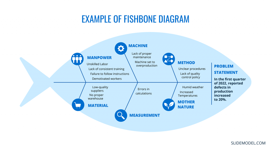
- Unskilled Labor
- Lack of consistent training
- Failure to follow instructions
- Demotivated workers
- Unclear procedures
- Lack of quality control policy
Measurement:
- Errors in calculations
- Lack of proper maintenance
- Machine set to overproduction
- Low-quality suppliers
- No proper warehouse
Mother Nature:
- Humid weather
- Increased Temperatures
Increase in customer complaints about product quality.
- Lack of training for employees
- Inadequate customer service skills
- Employee turnover affecting quality
- Inefficient quality control procedures
- Lack of clear product assembly guidelines
- Inadequate testing at different production stages
Product Design:
- Design flaws leading to defects
- Outdated machinery causing defects
- Lack of preventive maintenance leading to quality issues
Delays in project completion.
- Insufficient skilled project team
- Poor communication among team members
- Inadequate project management experience
- Unclear project scope and objectives
- Inadequate project planning and scheduling
- Lack of risk assessment and mitigation
- Inadequate budget allocation for project
- Limited availability of necessary resource
- Unreliable suppliers causing delays
External Factors:
- Regulatory changes impacting project
- Delays caused by adverse weather
Decrease in website traffic.
People/Skills:
- Lack of SEO knowledge among content creators and editors
- Inadequate social media marketing skills
Content Quality:
- Outdated and irrelevant website content
- Inadequate use of keywords for SEO
- Poorly written and unengaging content
Technical Issues:
- low website loading due to large images
- Broken links and frequent errors
- Ineffective mobile responsiveness
Marketing Strategies:
- Inconsistent promotion across platforms
- Lack of engagement with the target audience
- Ineffective use of online advertising
High employee turnover rate.
Work Environment:
- Poor workplace culture and lack of employee engagement
- Inadequate work-life balance
Management Practices:
- Ineffective leadership and communication
- Lack of recognition and rewards
- Inadequate opportunities for growth
Compensation:
- Below-market salaries and benefits
- Inadequate performance-based incentives
Recruitment and Hiring:
- Inaccurate job descriptions and expectations
- Insufficient screening of candidates
- Lengthy and inefficient hiring process
Pros and Cons of Fishbone Diagrams
Fishbone diagrams, also known as Ishikawa diagrams or cause-and-effect diagrams, are powerful tools for analyzing and solving complex problems. However, like any methodology, fishbone diagrams come with their own set of advantages and disadvantages. Let’s explore the pros and cons of using fishbone diagrams in problem-solving and decision-making processes.
- Visual Clarity: Fishbone diagrams provide a visual representation of the causes and effects of a problem, making it easier to understand the relationships between different factors.
- Holistic Analysis: They encourage comprehensive analysis by considering multiple categories of potential causes, ensuring a more thorough exploration of the problem.
- Structured Approach: Fishbone diagrams offer a structured framework for organizing thoughts and ideas, facilitating more organized problem-solving sessions.
- Collaborative Tool: They promote collaboration among team members by facilitating brainstorming sessions and encouraging diverse perspectives.
- Identification of Root Causes: Fishbone diagrams help in identifying the root causes of a problem, rather than just addressing its symptoms.
- Problem Prioritization: By categorizing causes and effects, teams can prioritize which issues to tackle first, leading to efficient problem-solving.
- Easy Communication: Fishbone diagrams provide a clear visual representation that can be easily shared with team members and stakeholders, enhancing communication.
- Data-Driven Analysis: They encourage data collection and analysis, enabling teams to make informed decisions based on evidence.
- Simplicity vs. Complexity: While fishbone diagrams work well for relatively simple problems, they might not be suitable for extremely complex issues with numerous interrelated causes.
- Subjective Interpretation: The process of categorizing causes and effects might involve subjective judgment, potentially leading to biased analysis.
- Overemphasis on Quantity: Focusing on listing numerous causes might divert attention from the most critical factors that require immediate attention.
- Time-Consuming: Constructing a fishbone diagram requires time, particularly when involving a large team. In time-sensitive situations, this can be a drawback.
- Limited to Known Causes: Fishbone diagrams rely on existing knowledge and may miss out on new or unexpected causes that were not previously considered.
- Complex Presentation: As the diagram becomes more intricate with more causes and categories, it might become difficult to interpret, defeating its purpose.
- Lack of Concrete Solutions: While fishbone diagrams identify causes, they don’t necessarily provide solutions. Further analysis is often required to determine the best course of action.
- Not a Standalone Solution: Fishbone diagrams are best used in conjunction with other problem-solving tools and methodologies for a well-rounded approach.
The purpose of a Fishbone Diagram Template is to inform the audience about the various problems affecting the company in a specific industry, and in turn, persuade them to present a plan of action to solve those problems.
A fishbone diagram can be visualized on paper, whiteboards, and even digitally with the help of digital whiteboards and presentations.
We recommend using Slide Model’s professionally designed 100% editable templates for PowerPoint and Google Slides to conduct a fishbone analysis.
From flat modern elements to a 3D perspective fishbone diagram, several different templates, including root cause analysis fishbone diagrams, can be used for conducting a root cause analysis, addressing problems, and presenting a solution to the team.
Here we have compiled a list of 100% editable fishbone diagram presentation templates that you can use for preparing presentations for cause & effect analysis.
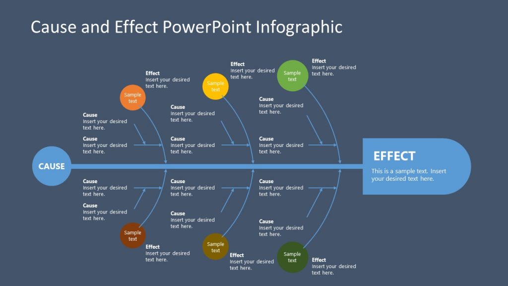
1. Fishbone Infographic PowerPoint Diagram
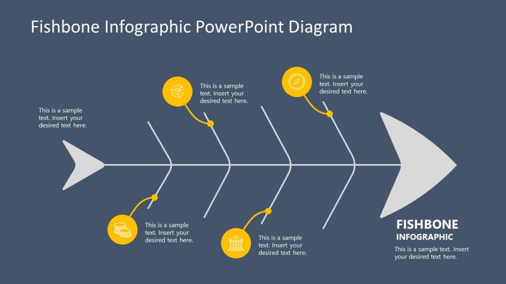
A fishbone infographic PowerPoint template is a creative depiction of the Ishikawa diagram. The bone structure is made for presenting 4 categories, identifying causes, and analyzing their effects to get to the root of any problem.
Use This Template
2. Fishbone Diagram Template 3D Perspective
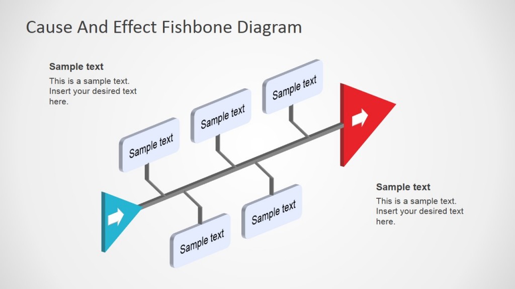
3D perspective fishbone template for PowerPoint and Google Slides is for conducting a cause and effect analysis in an appealing way and determining the root cause of the problem. Most likely factors can be presented with a proper analysis, while less impactful causes can be trimmed to reach the conclusion.
3. Animated 3D Fishbone PowerPoint Template
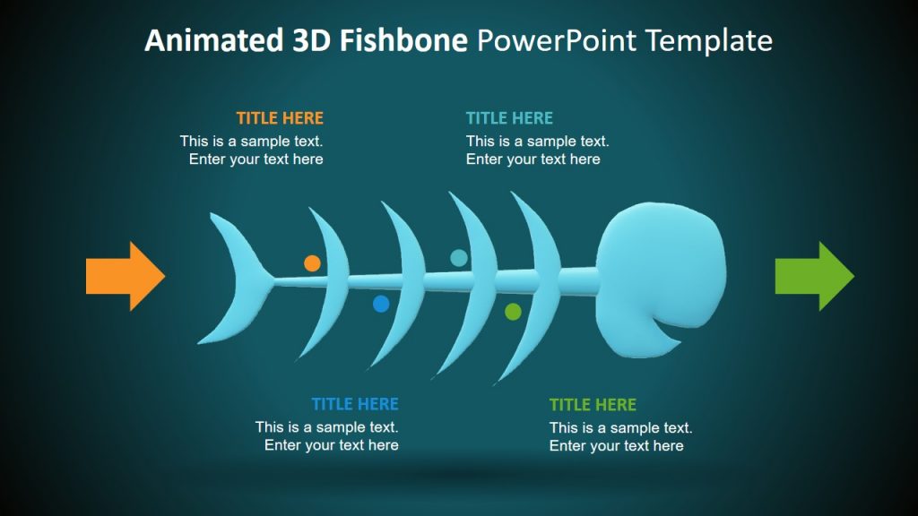
Another 3D template for the fishbone analysis that is fully compatible with PowerPoint and Google Slides can help managers present the root cause in any professional setting. The fishbone diagram is combined with 3D animations to create a realistic perspective making the RCA analysis interesting for the team.
4. Flat Fishbone Diagram for PowerPoint
This flat fishbone template is a professional presentation diagram for determining factors that are contributing to the problem. The analysis can be presented and summarized easily, while the template can also be used during real-time brainstorming sessions to create the fishbone diagram.
5. Cause and Effects PowerPoint Infographic Template
This cause and effect analysis template is for presenting a comprehensive look at the categories and their causes to determine the root cause of the problem. Fully customizable and compatible with PowerPoint and Google Slides, the template is a flat-vector-based Ishikawa diagram that enables teams to discuss project issues and drill down to the root cause of the problem.
6. Realistic Fishbone Diagram Template for PowerPoint
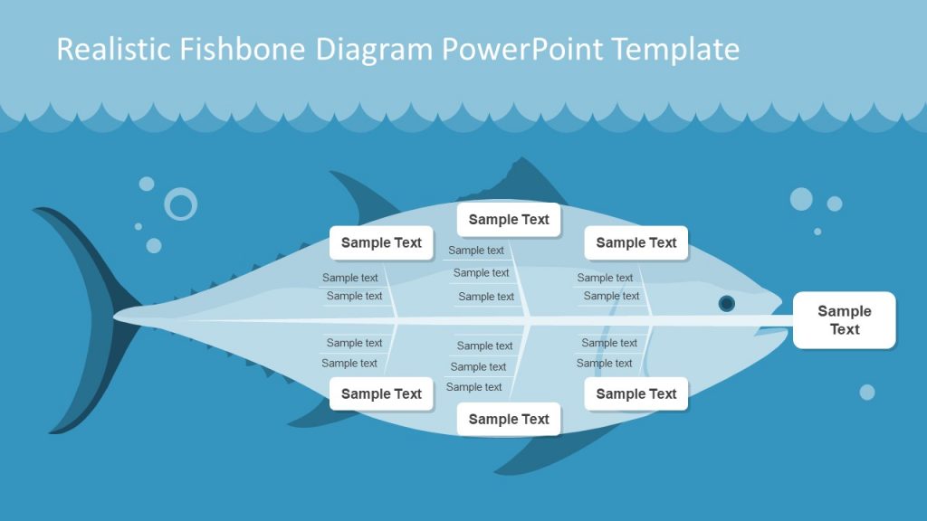
The realistic fish illustration in this fishbone template for PowerPoint and Google Slides can be used for analyzing problems, identifying root causes, and presenting solutions. Complex problems can be broken down to assist users in brainstorming and coming up with creative solutions for solving the problem.
7. Fishbone Template for PowerPoint
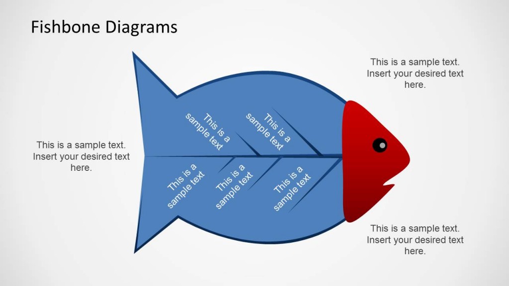
Another creative presentation template for the fishbone diagram that is helpful for conducting a root cause analysis (RCA) and presenting the cause and effect analysis results. The simple fish design makes the presentation engaging and memorable for the audience.
The fishbone analysis is a powerful tool for brainstorming potential causes of any problem and drilling down to the root cause for presenting a solution. It gives managers and teams a holistic look at the process categories and their issues and enables them to focus on areas that need to be fixed in order to minimize or eliminate the problem.
Our 100% editable fishbone diagram templates and root cause analysis templates made for PowerPoint and Google Slides are helpful for making professional presentations that can be used during brainstorming sessions, and also when presenting the solution after conducting the root cause analysis.
The simple-to-use, visual problem-solving tool is made to take corrective action with accurate analysis that can only be done while looking at the whole picture and improving processes by providing a framework for solving complex problems.

Like this article? Please share
Cause and Effect, Diagram Templates, Fishbone Analysis Filed under Business
Related Articles

Filed under Presentation Ideas • October 7th, 2023
Venn Diagram Ideas for PowerPoint Presentations
In this article, you will learn the basics of Venn diagrams, how they can be used in presentations and what type of information they are recommended for.
Filed under PowerPoint Tutorials • October 5th, 2023
How To Make Curved Arrows in PowerPoint
There are several methods by which you can make curved arrows for your presentations. In this article, we explain three different ways to draw arrows in PowerPoint.

• September 8th, 2023
Strategic Planning Process Templates For PowerPoint Presentations
Access a list of some very fine strategic planning process templates for PowerPoint that can be used for making business and academic presentations.
Leave a Reply
Advisory boards aren’t only for executives. Join the LogRocket Content Advisory Board today →
- Product Management
- Solve User-Reported Issues
- Find Issues Faster
- Optimize Conversion and Adoption
Cause and effect analysis with a fishbone (Ishikawa) diagram

Imagine you have been tasked with solving a problem: customers are experiencing lag while attempting to check out from their carts. Specifically, the app takes two minutes to transition from the cart page to the payment page once a customer clicks Continue .

What would you do? The first question that comes to mind is “why,” right? To answer this question, you’ll need to identify all the steps that customers take when checking out, and then assess how each step is performing. Together, these answers will enable you to determine the exact point in the checkout process where the problem is occurring.
This is called “root cause analysis” — you tried to list all the possibilities that could have created this problem. And out of all possibilities, you found which likely created the problem.
Let’s refer to the problem as the “effect,” and all the potential causes you identified during your analysis as the “causes.” Now, imagine trying to represent this cause-and-effect analysis visually. What types of diagrams could you create?
Maybe a tree whose roots are the effect and all the branches as the cause(s). Or maybe an Excel table listing all the causes and sub-causes in columns. Those are all good options, but in this article, we’ll discuss a cause-and-effect diagram (also called a fishbone diagram or Ishikawa diagram).
What is a fishbone diagram?
To start, a fishbone diagram (or Ishikawa diagram) is a tool to visually explore and represent the possible causes of an effect. The tool helps in identifying the potential causes that could have caused the problem.
A sample fishbone diagram looks like this:

It is called a fishbone as it looks like the skeleton of a fish. The head of the fish explains the problem statement (or the effect) and the bones attached explain the possible cause and sub-causes.
The history behind fishbone diagrams
Although the early history of fishbone analysis is slightly unclear, fishbone diagrams are believed to have been in use since the 1920s. However, it was during the 1960s that the diagram gained widespread popularity, thanks to the work of Dr. Kaoru Ishikawa on quality management processes for Kawasaki Shipyards.
It’s believed that Ishikawa first presented the fishbone analysis method in 1945, as part of the development of a company-wide quality control process. The creation of quality improvement processes and tools, along with the introduction of quality circles, played a significant role in the evolution of the concept of total quality management. The Ishikawa diagram became recognized as one of the seven basic quality tools.
When to use a fishbone diagram
The purpose of the fishbone diagram is to identify all the root causes of a problem. You can use fishbone analysis in product development — let’s list a few cases where you should use fishbone analysis:
- When you have to identify the possible causes of a problem
- When you have to develop a feature or product to fix the cause of a problem. This is a reverse analysis where business analysts find the gap in market need and fill that gap with a product or feature
- When evaluating a business process to find loopholes or gaps that create problems
- When you’re defining a process for quality control. Evaluate and find the current gap in quality and build processes to fill it
You can apply the fishbone analysis tool to most applications that need an establishment of quality control and management.
Now, we’ll go over the fishbone diagram and how you can apply it to multiple industries. Most businesses fall into one of these operation areas: services, manufacturing, and marketing, each of which can use a different fishbone diagram. While manufacturing may not be directly relevant to digital products, the fishbone diagram can still be a useful tool for uncovering problems and identifying potential causes. You can modify them accordingly to fit the context of your product.
Let’s start with the 4 Ws: what, why, when, and where. Applying these will help you find the possible potential causes for any effect. This is a good way to brainstorm and all fishbone diagrams must start with these, regardless of the industry you’re in. The 4 Ws are:
- What? There will be materials, products, lines of code, and other resources involved in the problem creation. Ask “what?” to help to pinpoint the specific components or resources that may be contributing to the issue
- Why? There will be situations or conditions that lead to the problem. Asking “why?” may help to uncover factors such as network failure, temperature, weather conditions, or other external considerations that may be impacting the system
- When? There will be a moment when a particular problem occurs. Ask “when?” to find out the time the problem occurs and figure out if it’s a recurring or isolated incident
- Where? Asking this question can help to identify specific areas, such as during the checkout process, a different part of the application, or within a specific context where the issue is most prominent.
Many businesses in the service industry indeed share similarities when it comes to cause analysis in their operational areas. Specifically, the 5 S’s (systems, suppliers, surroundings, safety, and skills) can be applied to cause and effect analysis within the service business.

Over 200k developers and product managers use LogRocket to create better digital experiences
While all service businesses don’t need to conduct a complete cause analysis using the 5 S’s, many find that these principles can be applied at the initial levels and then gradually approached more thoroughly as they identify potential causes within their unique environment:

Systems are the methods, policies, processes, products, and tools used to build operational excellence and provide service without any failure.
Suppliers are any issues in delivering the service itself, like lower quality of service, failure to support customers, delay in refunding payments, agents or vendors delay, and more.
Surroundings are any external factors such as market, competition, public relations, brand value/image, etc. that may contribute to the issue.
Skills focus on finding issues in training, qualifications, skill set, and the experience of employees providing the service.
Safety focuses on finding issues in the system’s overall safety, products, operational procedures, and work environment.
Though the 6 Ms apply mainly to the manufacturing industry, you can transfer this framework into the software industry as well. Since digital products don’t have physical parts, not all of them will be relevant, but we’ll highlight them anyway:

Material focuses on finding issues in any raw materials used for manufacturing. This includes issues with the quantity or quality of supplies, any issues with the timeline of procurement and supply, and more.
Method focuses on finding issues in processes, policies, regulations, training, and guidelines used by companies. Though this is relevant to manufacturing physical goods, these apply to digital products as well (in context).
Machine focuses on finding issues in machines that are used in manufacturing (production). This will help uncover any issues with the maintenance of machines, any failures in the machine or assembly line, etc.
Mother nature , aka the environment, focuses on finding issues in environmental conditions. For physical goods, this could mean issues with temperature, light conditions, etc. For digital products, this could mean issues with servers going down, weather causing latency problems, and more.
Manpower (aka people) focuses on finding issues in the workforce. This means any issues with the work itself, employee burnout, training and skill sets, and more.
Measurement focuses on finding issues in measuring the process and results. This is huge in any business, as metrics and measuring success are vital to the health of a company. Use this to find any issues in quality readings, calculations, and more.
There are 7 Ps that can be commonly applied in cause analysis. These are all related to marketing businesses, but nearly all physical and digital products have marketing functions that affect their product and that this can apply to:

People focuses on finding issues in people involved in marketing a product or service to customers. This implies issues with not targeting the right audience or marketers not having a good understanding of the product.
Product is focused on finding issues in the product or service of an organization. This could be several things, including the perceived image of the product , issues with availability to reach customers, or failure to meet customer needs .
Process works on finding issues in procedures for promoting and marketing the product or service. Are there any gaps in cross-functional team collaboration ? Are they any issues with the escalation matrix?
Price is a big one. This is where to uncover issues in the pricing of the product or service. Is the price too low? Maybe it’s too high? Are there any issues with the price range not matching the competition or with accepting certain payment methods?
Promotion focuses on finding issues in promotion methods, mediums, and strategies. Are social media advertisements reaching the right audience? Is it generating enough clicks?
Place identifies problems with the location of your product. Are there any issues with the availability of your product on particular devices?
Physical evidence is the last of the Ps. It focuses on finding issues in the direct visibility of your product or service. If it has a physical component, is there a problem with the packaging? Physical evidence literally implies any physical issues with the product getting into the hands of customers.
Advantages and disadvantages of fishbone diagrams
There are many advantages you carry when you use a fishbone diagram as a tool for your cause analysis, including:
- Simplicity : the visual representation is simple and easy to understand. Anyone who understands the problem can easily go through all the possible causes of that problem
- Flexibility : you can dissect the cause into sub-causes and go deeper to find the cause
- Associativity : any cause becomes a potential candidate to generate the effect. The relationship with the problem is tightly defined, helping you conclude your analysis
- Ease of use : it’s easy to brainstorm with a team and explain how to use the diagram. Everyone can instantly adapt and be involved in a brainstorm
- Fast : it helps you analyze the root causes quickly by applying the 5 Why’s and drill down potential causes
- Prioritization : visual representation helps you to prioritize your causes and narrow down the most important ones
There are also a few limitations that can make fishbone diagrams difficult to use, including:
- Causes may not be as relevant as you once thought. This could lead to confusion on the path forward or create another problem by accident
- If oversimplified, the fishbone analysis may not uncover what you’re looking for
- There’s potential to prioritize smaller causes over critical ones. Since prioritization is so easy, the team may focus on small causes and waste time in fixing them
- The more dissection into sub-clauses you do leads to more complex diagrams. These may eventually become messy and difficult to understand
- The analysis is mostly based on understanding and brainstorming. It needs additional evaluation of the cause, which in case all possibilities have to be evaluated, can become inefficient and time-consuming
Fishbone diagram template
If you’d like a fishbone diagram template to work with, you can download this one I made on Google Sheets . Feel free to make a copy of it and customize it for your own use.
If you’d like to try to create a fishbone diagram yourself for your own team and organization, here are some common steps to make and analyze it:
- Identify and write the effect (problem statement) as the fish head
- Brainstorm and identify major causes. Write a major cause on each side bone. These major causes can be the Ms, Ps, or S’s with regard to the industry you’re in, or a combination of multiple
- Brainstorm and identify sub-causes. Write the sub-cause on each smaller bone
- Check for completeness. Evaluate or review for too few causes or narrow it down if you have too many
- Analyze each potential cause to narrow it down further. The goal is to end up with one or more that need to be fixed
- Prioritize the potential cause based on its severity on the effect
Let’s draw the fishbone diagram for a digital product. We’ll use the problem we listed at the beginning where customers are facing problems during the checkout process:

While this list may not be comprehensive, it does cover many potential causes that could lead to delays in opening the payments page. It’s important to note that during a brainstorming session, many potential causes can arise, but it’s important to focus on the most likely causes to address first. In this case, we’ve highlighted a sub-cause in red that represents the result of the analysis and the area that should be addressed.
How product managers can use fishbone diagrams
There are many cases where product managers have to analyze the cause of a problem, and a fishbone diagram is a powerful tool for product managers to benefit from. Its easy and quick creation helps quickly narrow down potential causes and act upon them.
A few examples where product managers can make use of fishbone diagram are:
- Finding the root cause for a reduction in feature usage
- Finding the root cause of churn
- Learn the effects of new features on the application upfront
- Analyze what the team should focus on while prioritizing enhancements for a feature
- Presenting the quality measures taken on certain features to senior management
The process type fishbone diagram
A not-so-popular and not-so-in-use flavor for creating fishbone diagrams is the process-type fishbone diagram. It’s very similar but has a small change in the drawing:

The main bone of the fish is divided into multiple cause areas. Team brainstorms potential causes that could have created the problem in each of these areas. It is called process type because each area in the main bone (mostly) represents a process, but each area in the main bone also represents a department. Causes are explored in the process of each department as a result.
These diagrams are not that popular but are an efficient way to involve multiple cross-functional teams from various departments.
Kaoru Ishikawa popularized the fishbone diagram to analyze the root cause of any problem. It is also called the Ishikawa diagram or cause and effect diagram.
One can use the 4 Ws — what, why, when, and where — to begin cause analysis. Based on industry type, there are common areas of cause analysis: the 5 S’ for services, 6 Ms for manufacturing, and 7 Ps for marketing. If your company or product has a combination of these, you can create multiple fishbone diagrams to get to the root cause of your issue.
Featured image source: IconScout
LogRocket generates product insights that lead to meaningful action
Get your teams on the same page — try LogRocket today.
Share this:
- Click to share on Twitter (Opens in new window)
- Click to share on Reddit (Opens in new window)
- Click to share on LinkedIn (Opens in new window)
- Click to share on Facebook (Opens in new window)
- #product strategy

Stop guessing about your digital experience with LogRocket
Recent posts:.

Drive growth with these 7 customer feedback tools
A customer feedback tool is a software solution or platform designed to collect, analyze, and manage feedback from customers.

Leader Spotlight: Motivating teams to hit customer-centric outcomes, with Kristina Bailey
Kristina Bailey discusses the careful balance of knowing the business outcomes you want to achieve while balancing customer outcomes.

Exploring augmented products: Beyond the core offering
Augmented products leverage technology and additional services to provide enhanced functionality, convenience, and value to users.

A guide to acceptance test-driven development (ATDD)
ATDD is an agile methodology involving collaboration to define acceptance criteria before starting any development.

Leave a Reply Cancel reply
We use essential cookies to make Venngage work. By clicking “Accept All Cookies”, you agree to the storing of cookies on your device to enhance site navigation, analyze site usage, and assist in our marketing efforts.
Manage Cookies
Cookies and similar technologies collect certain information about how you’re using our website. Some of them are essential, and without them you wouldn’t be able to use Venngage. But others are optional, and you get to choose whether we use them or not.
Strictly Necessary Cookies
These cookies are always on, as they’re essential for making Venngage work, and making it safe. Without these cookies, services you’ve asked for can’t be provided.
Show cookie providers
- Google Login
Functionality Cookies
These cookies help us provide enhanced functionality and personalisation, and remember your settings. They may be set by us or by third party providers.
Performance Cookies
These cookies help us analyze how many people are using Venngage, where they come from and how they're using it. If you opt out of these cookies, we can’t get feedback to make Venngage better for you and all our users.
- Google Analytics
Targeting Cookies
These cookies are set by our advertising partners to track your activity and show you relevant Venngage ads on other sites as you browse the internet.
- Google Tag Manager
- Infographics
- Daily Infographics
- Popular Templates
- Accessibility
- Graphic Design
- Graphs and Charts
- Data Visualization
- Human Resources
- Beginner Guides
Blog Beginner Guides 15+ Fishbone Diagram Examples for Brainstorming Problem Causes
15+ Fishbone Diagram Examples for Brainstorming Problem Causes
Written by: Danesh Ramuthi Oct 13, 2023

The fishbone diagram, often referred to as the Ishikawa diagram or cause and effect diagram, is a powerful visualization tool that elucidates the intricate web of contributing factors behind a specific problem or issue. Characterized by its unique bone structure, it places the problem statement at the fish’s head, branching out to the various causes categorized into major segments.
The primary purpose of a fishbone diagram is to break down complex problems into understandable components, enabling team members to efficiently brainstorm and analyze causal relationships, making it indispensable in areas like quality management and root cause analysis.
Whether you’re aiming to delve deep into the causes of climate change or dissect the factors behind a the fishbone diagram provides a clear visual representation, highlighting the cause and effect relationship and underscoring the value of systematic problem solving.
For those eager to harness the potential of this great tool, Venngage offers a robust diagram maker . With customizable fishbone diagram templates , it empowers users to craft their diagrams effortlessly. These templates are meticulously designed to help you place ideas in the appropriate category, ensuring a comprehensive and organized cause and effect analysis.
Click to jump ahead:
Root cause fishbone diagram example
Cause and effect fishbone diagram example, ishikawa fishbone diagram example, medical fishbone diagram example, climate fishbone diagram example, project management fishbone diagram example, simple fishbone diagram example, how to use a fishbone diagram.
A root cause fishbone diagram, at its core, is a tool specifically tailored to identify, analyze and represent the underlying causes or root causes of a problem. Imagine a scenario where a manufacturing process has a recurring defect.

In such a scenario, the problem statement or defect would be placed at the fish’s head. As one begins the fishbone analysis, the spine of the fish represents the main flow of the process, with smaller bones branching out. Each of these bones corresponds to a contributing factor or potential cause of the defect.
Utilizing the fishbone diagram for root cause analysis involves gathering team members for a brainstorming session. Here, the group would identify various major categories like “Machinery”, “Manpower”, “Materials”, “Methods”, etc.

Under each of these categories, multiple factors are explored. For instance, under “Machinery”, potential causes could include outdated equipment, calibration errors or frequent breakdowns. The aim is to determine the root cause, or in some cases, multiple root causes, responsible for the defect.
The visual representation afforded by the diagram aids in systematically breaking down the problem, ensuring no stone is left unturned.

One of the advantages of using a root cause fishbone diagram is its ability to pinpoint areas that might otherwise be overlooked. It offers a structured approach, helping teams avoid short-term fixes and instead address the deeper, underlying issues. However, it’s crucial to be aware of its disadvantages too.
The success of the diagram heavily relies on the expertise and insights of the team members. If not all possible causes are considered, the analysis may be incomplete, leading to erroneous conclusions.
The cause and effect fishbone diagram is primarily used to map out the various causes contributing to a specific effect or outcome. For instance, consider a problem statement like “Decreased Sales in Quarter 3”.

Placed at the head of the fish, this statement becomes the focal point of the analysis. The spine extends outwards, branching into multiple categories that could be influencing this decline.
Starting with a brainstorming session, team members can identify major categories such as “Marketing”, “Product Quality”, “External Factors”, and “Customer Service”. Under “Marketing”, for example, potential causes could be insufficient advertising, poor social media engagement, or ineffective promotional campaigns.

The aim is to capture all the possible causes contributing to the decline in sales. Through the fishbone diagram’s structured format, teams can effectively map out the causal relationships, understanding how various factors interplay and lead to the overarching problem.
Using the cause and effect fishbone diagram offers a comprehensive overview, helping businesses or teams strategize effectively. They can prioritize areas that need urgent attention and develop strategies for improvement.

However, like all tools, it has its disadvantages. It requires thoroughness and can become convoluted if too many minor issues are included. Thus, it’s essential to keep the diagram focused on significant, impactful causes to maintain its efficacy as a problem-solving tool.
The Ishikawa fishbone diagram or just fishbone diagram, named after its creator Kaoru Ishikawa, is a powerful visualization tool designed to map out causal relationships concerning a particular problem or issue. Its unique design, reminiscent of a fish’s skeletal structure, places the primary problem or effect at the fish’s head.

From this focal point, the “spine” of the fish extends, leading to branching “bones.” Each branch represents a category or a group of potential contributing factors that lead to the main problem. Often used in root cause analysis and quality management, the Ishikawa diagram breaks down complex issues by categorizing them into major areas such as “People”, “Processes”, “Environment” and more.

This structure allows for an organized exploration of potential causes, ensuring that various perspectives and elements related to the problem are considered.
By facilitating systematic identification and categorization of causes, the Ishikawa fishbone diagram becomes an essential tool in problem-solving and decision-making processes.

In the medical realm, the fishbone diagram finds a specialized application, offering clinicians a structured format to diagnose and understand patient conditions.

Given the critical nature of healthcare, pinpointing the root causes of medical symptoms or conditions becomes paramount. A medical fishbone diagram aids in this by visualizing potential causes related to a specific medical problem or symptom. Categories in a medical context might include “Laboratory Results”, “Patient History”, “Physical Examination Findings” and “Environmental Factors”.

Under each category, various factors or sub-causes can be listed. For instance, “Laboratory Results” could delve into specifics like electrolyte imbalances or abnormal blood cell counts.

The diagram’s visual representation ensures that healthcare professionals can comprehensively analyze patient conditions, considering multiple facets before determining a diagnosis or treatment plan. This systematic approach fosters enhanced patient care and promotes more accurate diagnostic processes.
Designed for meticulous cause and effect analysis, this fishbone diagram delves into the complex problems associated with climate change. Its visual representation, characteristic of the fish’s skeletal structure, places the overarching problem statement — for instance, “Global Warming” — at the fish’s head. From here, multiple categories branch out, representing major aspects such as “Anthropogenic Activities”, “Natural Causes” and “Economic Factors”.
Each of these major categories further branches out to depict the specific factors contributing to the primary problem.

The strength of the climate fishbone diagram lies in its ability to present a comprehensive overview, ensuring that all potential causes, whether they relate to deforestation, industrial emissions, or natural volcanic activities, are captured and analyzed.
It serves as a visualization tool that aids researchers and decision-makers in crafting informed and effective strategies to combat climate-induced challenges.
In project management, where precision and systematic problem solving are paramount, the fishbone diagram finds significant utility. Project delays, cost overruns and unmet objectives often have multifaceted root causes.

The project management fishbone diagram, an adaptation of the Ishikawa diagram, serves to identify, categorize and analyze these causes.
Each category delineates into specific contributing factors, ensuring a thorough exploration of all potential issues. The visual format of the diagram aids team members during brainstorming sessions, facilitating the identification of challenges within the project lifecycle.

By offering a clear visual representation of the cause and effect relationships inherent in project challenges, the project management fishbone diagram stands as an invaluable tool, helping teams to preemptively address issues, optimize processes and enhance overall project execution.
Related: How to Write a Comprehensive Project Management Plan [+ Examples]
For problems that may not be as intricate but still require structured analysis, a simple fishbone diagram becomes the tool of choice. Stripped of excessive categories and branches, the simple fishbone diagram focuses on presenting the main causes of a problem in a straightforward manner.
Despite its simplicity, the core structure remains consistent: the primary issue or problem statement occupies the fish’s head, while a few major categories branch out from the central spine. This diagram’s strength lies in its accessibility; without delving into overly detailed branches, it offers a clear, concise visualization of the root causes and contributing factors.

It’s particularly beneficial for quick brainstorming sessions or when introducing the concept of cause and effect analysis to those unfamiliar with the fishbone methodology.
The simple fishbone diagram, while not exhaustive, provides a foundational framework, promoting structured thought and problem-solving in various contexts.
A fishbone diagram , also known as an Ishikawa or cause and effect diagram, provides a visual representation of potential causes leading to a particular problem or effect.
It is a structured brainstorming tool that helps teams identify, explore and visually display the many potential causes related to a specific problem.
- Begin your fishbone diagram with the problem statement or the main effect you’re trying to understand. This is written on the right side and represents the fish’s head.
- Draw a horizontal line extending from the problem statement towards the left. This is the fish’s spine and serves as a foundation for the potential causes.
- Identify the major categories of causes. Common categories include “People”, “Processes”, “Equipment”, “Materials” and others, depending on the context. These are the primary bones branching off the central spine.
- Draw diagonal lines or “fishbones” branching off the spine for each major category.
- Under each major category, brainstorm and list down the potential contributing factors or sub-causes. These represent the smaller bones branching out from the primary bones.
- Connect these sub-causes to the respective major category lines using smaller diagonal lines.
- For causes that may have sub-components or more detailed breakdowns, further branch out from the main cause.
- Make sure to clearly label each cause and sub-cause for clarity.
- After the brainstorming session, analyze the diagram to determine the most likely root causes of the problem.
- Once complete, your fishbone diagram should offer a comprehensive visual overview of all the potential causes leading to the main problem. This structure enables teams to better understand the problem, prioritize potential causes and develop effective solutions or interventions.
Related: 10+ Types of Diagrams and How to Choose the Right One
We explored over 15 examples of fishbone diagrams to help you effectively brainstorm the causes of problems.
This tool, with its visually intuitive structure, serves as a game-changer in analyzing root causes across various fields, from business challenges to technological snags.
This article doesn’t just present examples but also educates readers on how to harness the power of the fishbone diagram to its fullest.
For anyone inspired to create their own or seeking specialized templates, Venngage stands out as a go-to resource.
Explore Venngage’s diagram maker and discover an array of pre-designed fishbone diagram templates to kickstart your brainstorming sessions.
Discover popular designs

Infographic maker

Brochure maker

White paper online

Newsletter creator

Flyer maker
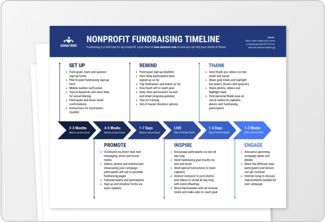
Timeline maker

Letterhead maker
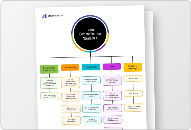
Mind map maker

Ebook maker
Diagramming Build diagrams of all kinds from flowcharts to floor plans with intuitive tools and templates.
Whiteboarding collaborate with your team on a seamless workspace no matter where they are., data generate diagrams from data and add data to shapes to enhance your existing visuals., enterprise friendly easy to administer and license your entire organization., security see how we keep your data safe., apps & integrations connect to all the tools you use from microsoft, google workspace, atlassian, and more..
- What's New Read about new features and updates.
Product Management Roadmap features, brainstorm, and report on development, so your team can ship features that users love.
Software engineering design and maintain complex systems collaboratively., information technology visualize system architecture, document processes, and communicate internal policies., sales close bigger deals with reproducible processes that lead to successful onboarding and training..
- Getting Started Learn how to make any type of visual with SmartDraw. Familiarize yourself with the UI, choosing templates, managing documents, and more.
- Templates get inspired by browsing examples and templates available in SmartDraw.
Diagrams Learn about all the types of diagrams you can create with SmartDraw.
Whiteboard learn how to combine free-form brainstorming with diagram blueprints all while collaborating with your team., data visualizers learn how to generate visuals like org charts and class diagrams from data., development platform browse built-in data visualizers and see how you can build your own custom visualization., open api the smartdraw api allows you to skip the drawing process and generate diagrams from data automatically., shape data add data to shapes, import data, export manifests, and create data rules to change dashboards that update..
- Explore SmartDraw Check out useful features that will make your life easier.
- Blog Read articles about best practices, find tips on collaborating, learn to give better presentations and more.
Support Search through SmartDraw's knowledge base, view frequently asked questions, or contact our support team.
Site license site licenses start as low as $2,995 for your entire organization..
- Team License The SmartDraw team License puts you in control with powerful administrative features.
Apps & Integrations Connect to all the tools you use.
- Contact Sales
What's New?

Solutions By Team
Save money, reduce hassle, and get more.
Unleash your team's productivity by combining enterprise-class diagramming, whiteboarding, and data while saving 10x over Visio and Lucidchart!

Getting Started Learn to make visuals, familiarize yourself with the UI, choosing templates, managing documents, and more.
Templates get inspired by browsing examples and templates available in smartdraw., developer resources, additional resources.

Team License The SmartDraw Team License puts you in control with powerful administrative features.
Solutions for your team.

Cause and Effect
Understand relationships quickly and easily with smartdraw's cause and effect or fishbone diagrams, what is a cause and effect diagram, cause and effect analysis, how to make a cause and effect diagram, cause and effect diagram tutorial, cause and effect chart examples, with smartdraw, you can create many different types of diagrams, charts, and visuals.
A cause and effect diagram examines why something happened or might happen by organizing potential causes into smaller categories. It can also be useful for showing relationships between contributing factors. One of the Seven Basic Tools of Quality, it is often referred to as a fishbone diagram or Ishikawa diagram.
One of the reasons cause & effect diagrams are also called fishbone diagrams is because the completed diagram ends up looking like a fish's skeleton with the fish head to the right of the diagram and the bones branching off behind it to the left.

To begin making a cause and effect diagram, write the main issue or problem to be analyzed in a box that is typically on the right edge of the page, halfway down the drawing area or page. A line called the "spine" or "backbone" should extend to the left starting from the edge of the main box (if you're using a SmartDraw template, this will already be there for you). Next, angle branches off of the spine, each representing a cause or effect of the main issue. Each of these branches can contain additional branches.

Most cause and effect diagrams examine a similar set of possible causes for any issue analyzed.
In the manufacturing industry, these are referred to as the 6Ms:
- Methods. Are there well-written and appropriate training guidelines in place? Are certain policies or regulations causing slow-downs or creating unnecessary steps?
- Machines. Are there any maintenance issues with the tools used or the number of tools available?
- Materials. Are there any issues getting raw materials from suppliers? Any problems with transportation (timing) or with the quality of the supplies?
- Measurements. Could there be errors in calculation or contamination that caused false readings? Could the way you measure be inconsistent in some way? Is your equipment regularly calibrated and maintained?
- Mother Nature/Environment. Is there too much moisture in the environment? Are temperatures too hot or too cold? Is there excessive dust or other contamination?
- Manpower/People. Do you have too little of your workforce devoted to a process? Are new people adequately trained? Is the training consistent? Are the right people with the right experience being hired or promoted? Is there a specific position creating a bottleneck or making frequent mistakes?
Occasionally, a manufacturing analysis will also include two other categories: Management and Maintenance.
In the service industry, these are described as the 4S:
- Surroundings. Does your establishment project the right image? Is it run-down? Is it impersonal? Is it comfortable?
- Suppliers. Are there any issues delivering your service? Do you have problems with low quality food deliveries? Are there too many dropped phone calls? Can your server handle traffic spikes? Are you getting enough traffic through advertising channels you're paying for?
- Systems. Do you have policies and procedures in place for all scenarios? Do you have modern cash registers that help your servers place orders and deliver checks efficiently?
- Skill. Are your employees properly trained? Do they have the right experience?

Occasionally, a fifth category will be included called "Safety".
In the marketing industry, cause and effect diagrams will often consist of 7Ps:
- Product. Consider all aspects of what you're selling including its quality, its perceived image, availability, warranties, support and customer service.
- People. When people buy your product or service they may interact with many people: sales people, customer service people, delivery people, and so on. Are there any potential problems with your company culture?
- Process/Procedure. How do you handle problems when they arise? Are they escalated properly? Is your staff trained appropriately and do they follow their training?
- Promotion. Consider advertising, sales, PR, branding, direct marketing, partnerships, and social media.
- Price. How does the price of your product or service compare to competitors? What discounts and payment methods are available?
- Physical evidence/Packaging. How is your product or service consumed? Is how or where you present your product hurting your ability to convert? Are your facilities clean and tidy? Is the packaging cheap or expensive?
- Place/Plant. Is your distribution efficient and cost-effective? Is your product sold in the right stores or neighborhoods? Are your stores convenient for your target customers?
How to Make Cause and Effect Diagrams with SmartDraw
SmartDraw makes creating cause and effect diagrams easy with built-in smart templates that let you add new causes in a single click and format your diagram automatically. Learn how by reading this cause and effect chart tutorial.

Best Practices in Cause and Effect Analysis
These are the best and most common practices when creating cause and effect diagrams.
- Identify the problem. Define the process or issue to be examined.
- Brainstorm. Discuss all possible causes and group them into categories.
- Draw the backbone. Once the topic is identified, draw a straight, horizontal line (this is called the spine or backbone) on the page, and on the right side, draw a rectangle at the end. Write a brief description of the problem in the rectangle.
- Add causes and effects. Causes are added with lines branching off from the main backbone at an angle. Write the description of the cause at the end of the branch. These are usually one of the main categories discussed above. Details related to the cause or effect may be added as sub-categories branching off further from the main branch. Continue to add branches and a cause or effect until all factors have been documented. The end result should resemble a fish skeleton.
- Analyze. Once the diagram has been completed, analyze the information as it has been organized in order to come to a solution and create action items.
Cause and Effect Examples
The best way to understand cause and effect diagrams is to look at some examples of cause and effect diagrams.
Click on any of these cause and effect diagrams included in SmartDraw and edit them:

Browse SmartDraw's entire collection of cause and effect examples and templates
More Cause and Effect Diagram Information
- Cause and effect diagram software
- Fishbone diagram maker
- Quality chart software
Try SmartDraw's Cause and Effect Diagram Software Free
Discover why SmartDraw is the best cause and effect diagram software today.
- Skip to main content
- Skip to primary sidebar
- Skip to footer
Additional menu
Cause and effect diagrams: what they are and how to use them
April 27, 2021 by MindManager Blog
By: Leanna Armstrong
Figuring out what lies at the root of a complicated production or work process challenge is sometimes easier said than done. Fortunately, a cause and effect diagram makes for a handy tool any time you’re called on to solve a problem or prevent one from happening.
What is a cause and effect diagram?
A cause and effect diagram is a visual map that functions as a problem-solving tool . As the name suggests, its main purpose is to help you identify the cause of a troubling situation in relation to the effect (or results) you’ve observed.
To clarify the cause and effect diagram definition further, it may help to understand that this tool is also known as a fishbone diagram . By setting your problem on one side – and radiating out to the various elements that may be causing it on the other – you end up with a diagram loosely resembling the skeleton of a fish.

How to use a cause and effect diagram
If you’re in any way involved in manufacturing or selling a product or service, chances are you can benefit from using a cause and effect diagram tool.
Fishbone diagrams are designed to help you:
- Get clear on the nature of a problem and why it’s occurring
- Identify contributing factors and how they’re connected
- Determine the best course of action for correcting a setback
You’ll get more from your cause and effect diagram if you and your team use it while brainstorming which areas of a particular process are most likely involved.
By visually breaking those areas down into their various components – and noting the impact of specific activities – you can increase your understanding of where things have gone wrong, and find a solution much faster.
You may discover, for example, that you need to:
- Change out materials or suppliers
- Revise the steps in a new or established workflow
- Tweak the tasks carried out by certain departments or individuals
With that in mind, here are 3 key areas where fishbone diagrams are commonly used.
1. Manufacturing a product.
This usually includes analyzing the 6 (or 8) M-factors involved in most production processes (Machinery, Method, Materials, Measurement, Mother Nature, Manpower, Management, Maintenance).
2. Providing a service.
This may include examining the 4 S-factors involved in many service delivery procedures (Surroundings, Suppliers, Skills, Systems).
3. Marketing a product or service.
This may include exploring the 8 P-factors involved in many product or service marketing systems (Price, People, Place, Product, Packaging, Procedures/Processes, Policies, Promotion).
No matter the source of your predicament, creating a cause and effect diagram template will help you and your team drill down and sort out the changes required to put it right.
How to create a cause and effect diagram
With a versatile program like MindManager , you can use a fishbone diagram template to capture, view, and organize all the potential causes of a problem – then use (and link to) an idea map for brainstorming ways to resolve it.
Here’s how to create a cause and effect diagram in 4 easy steps.
Label a box or node at one end of your diagram with the name of your issue (this represents the “head” of your fish).
Extend a main “spine” line from this node out to one side.
Add “rib” lines that branch off from either side of your main line, each leading to its own node. Label these nodes with the names of areas or factors that may be contributing to your problem.
Break down and explore each of these potential causes further by branching off to the specific processes, tasks, or resources involved (these are your sub-causes).
And that’s it!
Now, you and your team can spot suspect activity and identify the areas that are most likely causing your issue more easily. To better focus on problem-solving , you might even prioritize these factors by ranking them in the order in which they should be addressed.
Example of a cause and effect diagram
Creating a fishbone diagram is a great way to see what’s behind a particular problem so you can both resolve it and prevent it from occurring again. Here’s a simple cause and effect diagram example to help demonstrate this.
Let’s say you want to build out your line of travel backpacks and have recently launched a second product. Despite the success of your original backpack however, your new, sturdier pack is falling short of sales expectations .
You decide to investigate the problem from a marketing perspective with the help of a cause and effect diagram.
First, you identify the problem at hand by labeling a box on the middle left side of your diagram:

Next, at a loss for where to actually start, you construct the skeleton of your diagram by adding a spine line and branching out to all 8 areas of your marketing process:

At this point, you realize you should probably sit down with your promotional team and examine the key factors affecting these categories.
After some inspired brainstorming, the ribs of your diagram look like this:

As your team sits back and analyzes their finished diagram, 2 key findings emerge:
- Instead of travelers, your existing customers are predominantly students who love your product but can’t afford – and don’t want or need – a larger, heavier, more expensive version
- The travelers your new product was geared toward can buy a similar quality pack for significantly less from your local competitor
Now that you have a better understanding of the reasons behind your new pack’s lack of success, you can create a plan to resolve the problem (possibly by sourcing less costly materials) and ensure you always perform sufficient marketing research in future.
Cause and effect diagram use cases
Crafting a simple cause and effect diagram template is the best way to shift your team’s focus from the symptoms associated with a problem, to the construction of a practical plan for meeting it head-on.
Here are some simple use cases that illustrate a few more common cause and effect diagram examples.
Company A wants to fix a product quality problem
Production quality at the company’s newest widget manufacturing facility is below that of other locations. After ruling out factors in common, the QC team meets to create a cause and effect diagram around two key areas – Mother Nature (environment) and Manpower (plant workers) – and makes some impactful discoveries: the new plant is located in a very humid location where skilled labor is limited.
Making process adjustments to correct for the humidity and ramping up training allows the company to normalize quality.
Company B wants to resolve an image setback
As a newer massage and body treatment spa, image is especially important to the company. After a promising start, however, customer reviews show their reputation for calm and relaxation has taken a hit. Management sits down to brainstorm the problem and, with the help of a fishbone diagram, resolves that recent renovations and staff turnover have combined to disrupt the spa’s serene surroundings.
The company makes a plan to both confine renos to off-days and improve employee engagement.
Company C wants to overcome a marketing challenge
With a full line of successful breakfast cereals under their belt, the company is at a loss as to why their latest cereal isn’t selling. Working with their marketing department, they use a cause and effect diagram tool to pinpoint the problem and conclude that the only real difference lies in the packaging.
The company creates several new packaging designs and polls their target audience to determine which holds the greatest appeal.
Remember, mapping your way out of a problem is the easiest way to see where you are, how you got there, and what the most promising route is to get back on track.
Downloadable cause and effect diagram templates from MindManager
Click the images below to access the cause and effect diagram example shared above, and a blank template created using MindManager. Click “Menu” in the bottom left corner of your browser window, and then click “Download” to get a copy of the template. Open the template in MindManager to start working.
Don’t have MindManager? No worries! Try it free for 30 days.

Ready to take the next step?
MindManager helps boost collaboration and productivity among remote and hybrid teams to achieve better results, faster.
Why choose MindManager?
MindManager® helps individuals, teams, and enterprises bring greater clarity and structure to plans, projects, and processes. It provides visual productivity tools and mind mapping software to help take you and your organization to where you want to be.
Explore MindManager

How it works
For Business
Join Mind Tools
Video • 2 min read
Solving Problems With Cause and Effect Analysis
How to use cause and effect diagrams.
By the Mind Tools Content Team
Cause and Effect Analysis is a technique that helps you identify all the likely causes of a problem. This means that you can find and fix the main cause, first time around, without the problem running on and on.
The diagrams you create with this type of analysis are sometimes known as fishbone diagrams, because they look like the skeleton of a fish. The technique was developed by Professor Ishikawa in the 1960s.
To solve a problem with this technique, write down your problem in a box on the left-hand side of a piece of paper. Then draw a straight line from the box to the other side of the paper.
Once you've written down the problem, draw several lines that extend out from your long horizontal line. You're now going to brainstorm all of the factors that could be contributing to this problem. These may be systems, equipment, materials, external forces, people involved with the problem, and so on.
In this example, which looks at the issue of high staff turnover, the possible factors are management, the working environment, training and development, the corporate culture, and pay.
When you've brainstormed possible factors, draw several horizontal lines that extend outward from each one. You're now going to brainstorm possible causes of the problem, related each factor.
In this example, possible causes could be that managers micromanage their teams. They may not spend enough time on site. Or, they may not provide team members with the guidance they need to do their jobs effectively.
You repeat this for each of the factors that you identified in the last step, until you've identified all possible causes of the problem. From here, you can review all of these to identify the most likely cause.
Now, read the article that accompanies this video to learn more about Cause and Effect Analysis.
You've accessed 1 of your 2 free resources.
Get unlimited access
Discover more content
Cause and effect analysis.
Identifying the Likely Causes of Problems
Problem Solving
Add comment
Comments (0)
Be the first to comment!

Get 30% off your first year of Mind Tools
Great teams begin with empowered leaders. Our tools and resources offer the support to let you flourish into leadership. Join today!
Sign-up to our newsletter
Subscribing to the Mind Tools newsletter will keep you up-to-date with our latest updates and newest resources.
Subscribe now
Business Skills
Personal Development
Leadership and Management
Member Extras
Most Popular
Latest Updates

Tips for Dealing with Customers Effectively

Pain Points Podcast - Procrastination
Mind Tools Store
About Mind Tools Content
Discover something new today
Pain points podcast - starting a new job.
How to Hit the Ground Running!
Ten Dos and Don'ts of Career Conversations
How to talk to team members about their career aspirations.
How Emotionally Intelligent Are You?
Boosting Your People Skills
Self-Assessment
What's Your Leadership Style?
Learn About the Strengths and Weaknesses of the Way You Like to Lead
Recommended for you
Eight steps to effective business continuity management.
Eight Steps to Help Organiaztions Confront and Survive Potential Disasters
Business Operations and Process Management
Strategy Tools
Customer Service
Business Ethics and Values
Handling Information and Data
Project Management
Knowledge Management
Self-Development and Goal Setting
Time Management
Presentation Skills
Learning Skills
Career Skills
Communication Skills
Negotiation, Persuasion and Influence
Working With Others
Difficult Conversations
Creativity Tools
Self-Management
Work-Life Balance
Stress Management and Wellbeing
Coaching and Mentoring
Change Management
Team Management
Managing Conflict
Delegation and Empowerment
Performance Management
Leadership Skills
Developing Your Team
Talent Management
Decision Making
Member Podcast
- Demo Videos
- Interactive Product Tours
- Request Demo
Cause and Effect Analysis: Using Fishbone Diagram and 5 Whys
Cause and effect is a relationship between events or things, where one is the result of the other or others. This is a combination of action and reaction. A cause-and-effect analysis generates and sorts hypotheses about possible causes of problems within a process by asking participants to list all of the possible causes and effects for the identified problem.

What is a Fishbone Diagram?
Cause and effect analysis is often conducted by drawing cause-and-effect diagrams (also known as Fishbone Diagram), which organize a large amount of information by showing links between events and their potential or actual causes and provide a means of generating ideas about why the problem is occurring and possible effects of that cause.
The cause-and-effect analysis allows problem solvers to broaden their thinking and look at the overall picture of a problem. Cause-and-effect diagrams can reflect either cause that blocks the way to the desired state or helpful factors needed to reach the desired state.
Fishbone Diagram (also known as Cause and Effect Diagram or Ishikawa Diagram) It visually displays multiple causes for a problem and helps us to identify stakeholder ideas about the causes of problems which Allows us to immediately categorize ideas into themes for analysis or further data gathering. People often use the 5-whys technique in conjunction with the fishbone diagram.

When to Use a Fishbone Diagram?
A cause-and-effect analysis stimulates and broadens thinking about potential or real causes and facilitates further examination of individual causes. Because everyone’s ideas can find a place on the diagram, a cause-and-effect analysis helps to generate consensus about causes. It can help to focus attention on the process where a problem is occurring and to allow for constructive use of facts revealed by reported events.
- When identifying possible causes for a problem
- When having difficulty understanding contributing factors or causes of a system failure
- Most helpful as a team process for brainstorming collaboratively
Steps for Creating a Fishbone Diagram
- Identify the problem statement (also referred to as the effect).
- Written at the mouth of the fish
- Identify the major categories of causes of the problem
- Written as branches from the main arrow for each of the major categories include: equipment or supply factors, environmental factors, rules/policy/procedure factors, and people/staff factors
- Brainstorm all the possible causes of the problem
- Ask “why does this happen?”
- Write it as a branch from the appropriate category
- Repeat the other categories by asking “Why does this happen?” about each cause
- Write sub-causes branching off the cause branches
- Ask “Why?” and generate deeper levels of causes and continue organizing them under related causes or categories
Use 5 Whys in Combination with Fishbone Diagram
The 5 Whys can be used individually or as a part of the fishbone (also known as the cause and effect or Ishikawa) diagram. The fishbone diagram helps you explore all potential or real causes that result in a single defect or failure. Once all inputs are established on the fishbone, you can use the 5 Whys technique to drill down to the root causes.
For example:
Statement – Your car stops in the middle of the road.
1. Why did your car stop?
- Because it ran out of gas.
2. Why did it run out of gas?
- Because I didn’t buy any gas on my way to work.
3. Why didn’t you buy any gas this morning?
- Because I didn’t have any money.
4. Why didn’t you have any money?
- Because I lost it all last night in a poker game.
5. Why did you lose your money in last night’s poker game?
- Because I’m not very good at “bluffing” when I don’t have a good hand.
As you can see, in both examples the final Why leads the team to a statement (root cause) that the team can take action upon. It is much quicker to come up with a system that keeps the sales director updated on recent sales or teach a person to “bluff” a hand than it is to try to directly solve the stated problems above without further investigation.
Turn every software project into a successful one.
We use cookies to offer you a better experience. By visiting our website, you agree to the use of cookies as described in our Cookie Policy .
© 2024 by Visual Paradigm. All rights reserved.
- Privacy statement
How to Use Cause and Effect Analysis to Solve Business Problems
Updated on: 24 July 2023
Every business has its own problems, big and small.
A problem in your business can be an opportunity for the business to grow or can be the setback that leads to failure. It all depends on how you embark on problem-solving.
A good way of preventing the occurrence of undesirable things is by proper analysis of the business situation, identification of the root causes and solving the situation. Hence the need to have an efficient and effective cause and effect analysis . Here we offer you a clear guide on how to go about it.
How to Do a Cause and Effect Analysis

Cause and effect analysis is also known as a fishbone diagram . It was developed by Professor Kaoru Ishikawa, a pioneer professional in the field of quality management in the 1960s.
The diagram is called fishbone as its final look is in the form of a fishbone. It was initially used for quality improvement but it can also be helpful in analyzing business processes through the identification of its causes and hindrances, as well as on ways to improve it.
The cause and effect analysis basically involves two key steps which are looking backward and looking forward.
- In looking backward, the analysis focuses on identifying areas in which mistakes were made or money was lost. It looks into what had happened before. In identifying where the issues are, you are able to work towards avoiding the problem in the future. Another advantage of this is that, you’ll be able to replicate a positive outcome.
- Looking into the future and planning for it, the analysis seeks to find workable solutions that are to be implemented in the future and build on the future success of the business. This analysis enables you to determine your future outcome by planning what to do now to achieve it.
This method is unique in that it encourages creative thinking as well as brainstorming in the process of breaking down issues and aligning them in the process of finding its solutions.
Among the key advantages of this method is that it ensures that you don’t seek out to solve the wrong problems, it also ensures that you solve the problem well enough for it to go away.
Step 1: Problem Identification
The way to use this tool is very simple. You first need to identify the problem area that needs analysis. A good way to do this is by giving a brief description of the current business situation and the consequences as well as the reasons for why they occurred.
Here you can replace the problem with a goal that you want to achieve. For instance, high profitability. You need to be very specific about the problem that you’re facing as this forms the basis of your analysis. If the identification is wrong, then the analysis also tends to be wrong.
You should also identify the people involved as well as what the exact problem is and how it occurs. For example, low productivity due to absenteeism especially in the production department, which includes production personnel and the line manager, for the period from January to November 2017.
Step 2: Main Problem Causes

The next step is identifying the main causes of the problem, for example, the people, the procedures your business utilized as well as the materials or equipment. Here, you will need to do a lot of brainstorming to come up as many reasons as you possibly can.
You can use various models to help you identify as many problems as you can in a clear manner. For example, the McKinsey 7S Framework which includes, Strategy, Systems, the business Structures, Shared values of the business, Staff, Skills, and Style.
Step 3: Identify Plausible Sub-causes of the Main Causes
Thereafter, you can narrow down to further plausible causes of the main problems that you’ve listed. This is important for the problem-solving stage of analyzing the diagram, as you will know what to do exactly to rectify the situation. This can include issues like wrong norms and values that could be as a result of poor training of employees.
Step 4: Analyze the Diagram

By now, your diagram should be showing all the main and minor causes that you’ve thought of.
Depending on how complex the information is, you can do a much deeper investigation on the causes. This can be by conducting a survey as well as drawing up questionnaires.
For example, you can ask your employees to fill in a survey on how much they understand the products you sell in your business. The information you get from this will help you build upon areas of training in order to address the problem of lack or insufficient knowledge.
From here, a corresponding step is developing an action plan with clear priorities that can be implemented immediately. This is made simple as the plans can comprise of actions to solve the subproblem causes.
For the action plan to be effective, it needs to be clear and to be executed aggressively. For example, a sub cause like lack of staff morale can be turned into an action plan, which will be giving incentives for staff motivation, hence, improved productivity and in turn higher profitability which was the main goal.
Ready to Use Cause and Effect Analysis in Business Problem-Solving?
The cause and effect analysis uses brainstorming and critical analysis by way of visual representation to enable problem-solving .
The main problem is drawn out on the left while the main causes are drawn out an extension of the problem. This then calls for a look at the sub causes which are written out as branches of the main problems.
Various models are also used as a guide to identifying the problem-causes. The models look into various business elements including, the people relation the processes, the systems and equipment use, the management as well as the general organizational structure.
Among the advantages of this analysis method include correct identification of problem-causers hence proper problem-solving, better visualization and hence the effectiveness of the problem-solving process.
Would you like to try drawing up your own Fishbone Diagram ?
BIO : Lori Wade is the content writer and a career specialist for college students. She is a content marketer, sharing experience in writing, education, and self-development in her publications, for example, https://eliteessaywriters.com/blog/toefl-essay-topics/ . Connect with her on Facebook and follow her on Twitter .
Join over thousands of organizations that use Creately to brainstorm, plan, analyze, and execute their projects successfully.

More Related Articles

Thanks for sharing your thought! Helps me a lot to do the same thing in my company. I agree that before you decide what o plan you need to have to weigh its cause and effect.
Leave a comment Cancel reply
Please enter an answer in digits: 5 + 1 =
Download our all-new eBook for tips on 50 powerful Business Diagrams for Strategic Planning.
- Join Mind Tools

Cause and Effect Analysis
Identifying the likely causes of problems, (also known as cause and effect diagrams, fishbone diagrams, ishikawa diagrams, herringbone diagrams, and fishikawa diagrams.).
When you have a serious problem, it's important to explore all of the things that could cause it, before you start to think about a solution.
That way you can solve the problem completely, first time round, rather than just addressing part of it and having the problem run on and on.
Cause and Effect Analysis gives you a useful way of doing this. This diagram-based technique, which combines Brainstorming with a type of Mind Map , pushes you to consider all possible causes of a problem, rather than just the ones that are most obvious.
Click here to view a transcript of this video.
About the Tool
Cause and Effect Analysis was devised by professor Kaoru Ishikawa, a pioneer of quality management, in the 1960s. The technique was then published in his 1990 book, " Introduction to Quality Control ."
The diagrams that you create with are known as Ishikawa Diagrams or Fishbone Diagrams (because a completed diagram can look like the skeleton of a fish).
Although it was originally developed as a quality control tool, you can use the technique just as well in other ways. For instance, you can use it to:
- Discover the root cause of a problem.
- Uncover bottlenecks in your processes.
- Identify where and why a process isn't working.
How to Use the Tool
Follow these steps to solve a problem with Cause and Effect Analysis:
Step 1: Identify the Problem
First, write down the exact problem you face. Where appropriate , identify who is involved, what the problem is, and when and where it occurs.
Finding This Article Useful?
You can learn another 44 problem-solving skills, like this, by joining the Mind Tools Club.

Subscribe to Our Newsletter
Receive new career skills every week, plus get our latest offers and a free downloadable Personal Development Plan workbook.
Then, write the problem in a box on the left-hand side of a large sheet of paper, and draw a line across the paper horizontally from the box. This arrangement, looking like the head and spine of a fish, gives you space to develop ideas.
In this simple example, a manager is having problems with an uncooperative branch office.
Figure 1 – Cause and Effect Analysis Example Step 1

(Click image to view full size.)
Some people prefer to write the problem on the right-hand side of the piece of paper, and develop ideas in the space to the left. Use whichever approach you feel most comfortable with.
It's important to define your problem correctly. CATWOE can help you do this – this asks you to look at the problem from the perspective of Customers, Actors in the process, the Transformation process, the overall World view, the process Owner, and Environmental constraints.
By considering all of these, you can develop a comprehensive understanding of the problem.
Step 2: Work Out the Major Factors Involved
Next, identify the factors that may be part of the problem. These may be systems, equipment, materials, external forces, people involved with the problem, and so on.
Try to draw out as many of these as possible. As a starting point, you can use models such as the McKinsey 7S Framework (which offers you Strategy, Structure, Systems, Shared values, Skills, Style and Staff as factors that you can consider) or the 4Ps of Marketing (which offers Product, Place, Price, and Promotion as possible factors).
Brainstorm any other factors that may affect the situation.
Then draw a line off the "spine" of the diagram for each factor, and label each line.
The manager identifies the following factors, and adds these to his diagram:
Figure 2 – Cause and Effect Analysis Example Step 2

Step 3: Identify Possible Causes
Now, for each of the factors you considered in step 2, brainstorm possible causes of the problem that may be related to the factor.
Show these possible causes as shorter lines coming off the "bones" of the diagram. Where a cause is large or complex, then it may be best to break it down into sub-causes. Show these as lines coming off each cause line.
For each of the factors he identified in step 2, the manager brainstorms possible causes of the problem, and adds these to his diagram, as shown in figure 3.
Figure 3 – Cause and Effect Analysis Example Step 3

Step 4: Analyze Your Diagram
By this stage you should have a diagram showing all of the possible causes of the problem that you can think of.
Depending on the complexity and importance of the problem, you can now investigate the most likely causes further. This may involve setting up investigations, carrying out surveys, and so on. These will be designed to test which of these possible causes is actually contributing to the problem.
The manager has now finished his analysis. If he hadn't looked at the problem this way, he might have dealt with it by assuming that people in the branch office were "being difficult."
Instead he thinks that the best approach is to arrange a meeting with the Branch Manager. This would allow him to brief the manager fully on the new strategy, and talk through any problems that she may be experiencing.
A useful way to use this technique with a team is to write all of the possible causes of the problem down on sticky notes. You can then group similar ones together on the diagram.
This approach is sometimes called CEDAC (Cause and Effect Diagram with Additional Cards) and was developed by Dr. Ryuji Fukuda, a Japanese expert on continuous improvement.
Professor Kaoru Ishikawa created Cause and Effect Analysis in the 1960s. The technique uses a diagram-based approach for thinking through all of the possible causes of a problem. This helps you to carry out a thorough analysis of the situation.
There are four steps to using the tool.
- Identify the problem.
- Work out the major factors involved.
- Identify possible causes.
- Analyze your diagram.
You'll find this method is particularly useful when you're trying to solve complicated problems.
This site teaches you the skills you need for a happy and successful career; and this is just one of many tools and resources that you'll find here at Mind Tools. Subscribe to our free newsletter , or join the Mind Tools Club and really supercharge your career!
Rate this resource
The Mind Tools Club gives you exclusive tips and tools to boost your career - plus a friendly community and support from our career coaches!

Comments (36)
- Over a month ago BillT wrote Hi AnotherFrancis, and Welcome to the Club! As with my response to Alex81, not everyone will find the example the most useful, as is the case with you. We appreciate your feedback. BillT Mind Tools Team
- Over a month ago AnotherFrancis wrote Nice article but, like Alex81, I didn't find the example to be very helpful.
- Over a month ago BillT wrote Hi Alex81, and Welcome to the Club! Thank you for your feedback on the Cause and Effect Analysis. I agree that not everyone may find the example the best way to demonstrate the resource. This diagram has also been known as the Ishikawa Diagram or Fishbone Diagram. You may find additional resources with better examples for you. Also, you may wish to post this in the Forums so that our members can provide their input into the topic. BillT Mind Tools Team
Please wait...
- Managing Your Finances Effectively
- Identifying Patterns: A Practical Guide
Crossword Puzzles and Sudoku: A Problem-Solving Exploration
Exploring online whiteboarding tools for brainstorming.
- Analytical problem solving
- Identifying root causes
- Analyzing consequences
- Brainstorming solutions
- Heuristic problem solving
- Using analogies
- Applying existing solutions
- Trial and error
- Creative problem solving
- Mind mapping
- Brainstorming
- Lateral thinking
- Research skills
- Interpreting information
- Data collection and analysis
- Identifying patterns
- Critical thinking skills
- Recognizing bias
- Analyzing arguments logically
- Questioning assumptions
- Communication skills
- Negotiation and compromise
- Listening skills
- Explaining ideas clearly
- Planning techniques
- SWOT analysis
- Gantt charting
- Critical path analysis
- Decision making techniques
- Force field analysis
- Paired comparison analysis
- Cost-benefit analysis
- Root cause analysis
- Five whys technique
- Fault tree analysis
- Cause and effect diagrams
- Brainstorming techniques
- Brainwriting
- Brainwalking
- Round-robin brainstorming
- Creative thinking techniques
- Serendipity technique
- SCAMPER technique
- Innovation techniques
- Value innovation techniques
- Design thinking techniques
- Idea generation techniques
- Personal problems
- Deciding what career to pursue
- Managing finances effectively
- Solving relationship issues
- Business problems
- Increasing efficiency and productivity
- Improving customer service quality
- Reducing costs and increasing profits
- Environmental problems
- Preserving natural resources
- Reducing air pollution levels
- Finding sustainable energy sources
- Individual brainstorming techniques
- Thinking outside the box
- Word association and random word generation
- Mind mapping and listing ideas
- Group brainstorming techniques
- Synectics technique
- Online brainstorming techniques
- Online whiteboarding tools
- Virtual brainstorming sessions
- Collaborative mind mapping software
- Team activities
- Group decision making activities
- Debate activities and role-play scenarios
- Collaborative problem solving games
- Creative activities
- Creative writing exercises and storyboards
- Imagination activities and brainstorming sessions
- Visualization activities and drawing exercises
- Games and puzzles
- Crossword puzzles and Sudoku
- Logic puzzles and brain teasers
- Jigsaw puzzles and mazes
- Types of decisions
- Structured decisions
- Simple decisions
- Complex decisions
- Problem solving techniques
- Cause and Effect Diagrams: A Problem-Solving Technique
A comprehensive guide to understanding and utilizing cause and effect diagrams for problem solving and root cause analysis.

Cause and effect diagrams are a powerful problem-solving technique that can help you identify the root cause of any issue, from small everyday annoyances to complex organizational problems. By following a systematic process of gathering data, analyzing it and then developing solutions, cause and effect diagrams can be used to effectively tackle any problem that you may face. This article will provide an overview of the cause and effect diagram technique, outlining how it works and the steps involved in using it. We will also look at some examples of how it can be used to solve a variety of problems. When trying to solve a problem, it is important to break down all the possible causes.
A cause and effect diagram is a visual tool used to represent all the possible causes of a problem or event. It can be used to brainstorm different causes in order to identify the root cause of a problem. The process of creating a cause and effect diagram begins by identifying the problem or event, then listing all the possible causes that could be contributing to it. The causes can then be grouped together into categories.
For example, if the problem is a defect in a product, the categories might include “materials”, “suppliers”, “manufacturing process”, “transport”, etc. After the categories have been identified, arrows can be added to show the relationship between each cause and the effect. Once the cause and effect diagram is complete, it can be used to identify potential causes and solutions. By looking at the diagram as a whole, it is possible to identify which causes may have the most impact on the problem.
This can help narrow down potential solutions and make it easier to identify the root cause of a problem. There are several benefits of using cause and effect diagrams in problem-solving. First, they provide an organized way of looking at problems. By breaking down each component of the problem, it is easier to identify potential causes and solutions. Second, cause and effect diagrams can help individuals think more creatively about problems.
Benefits of Cause and Effect Diagrams
• they are useful for documenting problems and their solutions, which can be helpful when troubleshooting future issues., creating a cause and effect diagram.
Next, list all possible causes that could contribute to the problem or event. This includes both direct and indirect causes. Then, similar causes should be grouped into categories . This helps to narrow down the potential causes and makes the diagram easier to read.
After this, arrows should be added to show the relationship between each cause and the effect. Finally, the diagram should be reviewed as a whole to identify potential causes and solutions . Cause and effect diagrams can be an invaluable tool for problem solving and root cause analysis. By taking the time to create a diagram, individuals can better understand the various factors that may be contributing to a problem or event and identify potential solutions.
Cause and effect diagrams are an invaluable tool for problem solving and root cause analysis. By organizing problems into component parts, they allow individuals to think more creatively and identify potential causes and solutions more effectively. Furthermore, they provide a documented record of the problem and its solution for future reference. By following these steps, individuals can use cause and effect diagrams to effectively solve problems.

- Visualization Activities and Drawing Exercises
Learn more about visualization activities and drawing exercises, from problem-solving activities to creative activities.

- Questioning Assumptions: A Critical Thinking Skill
Understand the importance of questioning assumptions and learn to use it as an effective critical thinking skill when problem solving.

- Collaborative Mind Mapping Software
Learn about collaborative mind mapping software, the benefits of using it, and some of the best tools available.

- Exploring the SCAMPER Technique for Creative Problem Solving
Learn how to use the SCAMPER technique to come up with creative solutions to problems.
- Mind Mapping - Creative Problem Solving and Creative Thinking Techniques
- Using Analogies to Solve Problems
- Negotiation and Compromise
- Identifying Root Causes
- Value Innovation Techniques
- Brainwriting: A Creative Problem-Solving Technique
- Choosing the Right Career: Problem-Solving Examples
- Cost-benefit Analysis: A Guide to Making Informed Decisions
- Making Complex Decisions: A Comprehensive Overview
- Mind Mapping and Listing Ideas
- Finding Sustainable Energy Sources
- Debate Activities and Role-Play Scenarios
- Brainstorming: A Comprehensive Look at Creative Problem Solving
- Exploring Trial and Error Problem Solving Strategies
- Exploring Lateral Thinking: A Comprehensive Guide to Problem Solving Strategies
- Data Collection and Analysis - Problem Solving Skills and Research Skills
- Word Association and Random Word Generation
- Creative Writing Exercises and Storyboards
- Analyzing Arguments Logically
- Solving Relationship Issues
- Group Decision Making Activities
- Reducing Air Pollution Levels
- Thinking Outside the Box: An Overview of Individual Brainstorming Techniques
- SWOT Analysis: A Comprehensive Overview
Jigsaw Puzzles and Mazes: Problem Solving Activities for Fun and Learning
- Brainwriting: A Group Brainstorming Technique
- Simple Decisions - An Overview
- Idea Generation Techniques: A Comprehensive Overview
- Imagination Activities and Brainstorming Sessions
- Round-robin brainstorming: Exploring a Group Brainstorming Technique
- Five Whys Technique: A Comprehensive Analysis
- Design Thinking Techniques: A Comprehensive Overview
- Gantt Charting: A Primer for Problem Solving & Planning Techniques
- Preserving Natural Resources
- Paired Comparison Analysis: A Comprehensive Overview
- Analyzing Consequences: A Problem Solving Strategy
- Reducing Costs and Increasing Profits: A Problem Solving Example
- Interpreting Information: A Problem-Solving and Research Skills Primer
- Improving Customer Service Quality
- Collaborative Problem Solving Games: Exploring Creative Solutions for Teams
- Structured Decisions: An Overview of the Decision Making Process
- Critical Path Analysis: A Comprehensive Guide
- How to Explain Ideas Clearly
- Fault Tree Analysis: A Comprehensive Overview
- Logic Puzzles and Brain Teasers: A Comprehensive Overview
- Mind Mapping: A Creative Problem Solving Tool
- Force Field Analysis for Problem Solving and Decision Making
- Maximizing Efficiency and Productivity
- Exploring Brainwalking: A Creative Problem-Solving Technique
- Applying Existing Solutions for Problem Solving Strategies
- Virtual Brainstorming Sessions: A Comprehensive Overview
- Brainstorming Solutions: A Problem-Solving Guide
- Round-robin Brainstorming: A Creative Problem Solving Tool
- Exploring the Serendipity Technique of Creative Problem Solving
- Listening Skills: A Comprehensive Overview
- Exploring Synectics Technique: A Comprehensive Guide
- Recognizing Bias: A Problem Solving and Critical Thinking Skills Guide
New Articles

Which cookies do you want to accept?

- Dr. Juran’s History
- Dr. Joseph A. DeFeo
- Need a Speaker?
- The Juran Excellence Model
- The Juran Roadmap
- Quality by Design (QbD) & DFSS
- Conintuous Improvement
- Quality Control & Assurance
- LSS Certification
- Certification Project Reviews
- Coaching Support
- Training & Consulting
- IMPRO Online Learning
- Organizational Assessments
- Lean Six Sigma Yellow Belt
- Lean Six Sigma Green Belt
- Upgrade to LSS Black Belt
- Lean Six Sigma Black Belt
- Lean Six Sigma MBB
- Lean Expert Program
- Root Cause Analysis
- Quality Auditor
- Certified Quality Director
- Quality By Design Green Belt
- Introduction to Statistics
- Hypothesis Testing
- Design of Experiments
- Measurement System Analysis
- Leadership for Quality
- Launching Effective Teams
- Facilitation Skills for Project Leaders
- Training the Adult Learner
- Quality Leadership Certification
- Champion Training
- Making Quality Happen
- COQ & COPQ
- Food Processing
- Healthcare and Hospitals
- Manufacturing
- Pharmaceutical
- Higher Education
- Project Case Study Examples
- Juran Quality Handbook
- Hot Topic Webinars
- Published Papers
- Quality Minute Videos
The Ultimate Guide to Cause and Effect Diagrams
Juran May 1, 2018 Blog , The Lean Six Sigma DMAIC Steps Leave a Comment
What is a “Cause and Effect Diagram”?
A cause-effect diagram is a visual tool used to logically organize possible causes for a specific problem or effect by graphically displaying them in increasing detail, suggesting causal relationships among theories. A popular type is also referred to as a fishbone or Ishikawa diagram. Cause-Effect can also be diagrammed using a tree diagram.
When diagnosing the cause of a problem, a cause-effect diagram helps to organize various theories about root causes and presents them graphically.
The C-E Diagram is a fundamental tool utilized in the early stages of an improvement team. The ideas generated during a brainstorming or affinity process are used to populate the diagram. Since the list of issues on a C-E may be very large, the team should use a prioritization or multi-vote technique to narrow the list of potential cause that they desire to investigate farther.
At the head of the diagram is the “Effect” that the team is investigating. The team brainstormed potential causes for this effect. The skeleton becomes the various potential causes and the headers are the column heads from the affinity diagram.
Cause and Effect Diagram Examples
A simple cause-effect diagram is shown in Figure 29. The phenomenon to be explained is “Lost control of car.” Some of the possible major factors contributing to that lost control are a flat tire, a slippery road, mechanical failures, and driver error. Each of these major categories of causes may, in turn, have multiple causes. A flat tire may come from a nail, a rock, glass, or a blow-out from material failure. The causal relationship can be traced back still more steps in the causal chain if necessary or appropriate. Lost control may arise from a mechanical failure; that failure may be a brake failure, which, in turn, may come either from fluid loss or from worn pads. You can probably think of other factors to add to this diagram.
Cause and Effect Diagram Example: Lost Control of Car

As we can see from Figure 29 , this tool has three prominent basic features:
- It is a visual representation of the factors that might contribute to an observed effect or phenomenon that is being examined.
- The interrelationships among the possible causal factors are clearly shown. One causal factor may appear in several places in the diagram. For example, if temperature affects both moisture content and physical dimensions, then temperature would appear in both places.
- The interrelationships are generally qualitative and hypothetical.
A cause-effect diagram is usually prepared as a prelude to developing the data needed to establish causation empirically.
Cause and Effect Tree Diagram Example: Lost Control of Car
The cause-effect tree is conceptually similar to the cause-effect diagram. It is sometimes easier to construct, and some computer software packages have adopted this form. Figure 30 reproduces the contents of Figure 29 in a tree form.

Cause and Effect Diagram Key Concepts
- A cause-effect diagram cannot identify a root cause; it presents graphically the many causes that might contribute to the observed effect.
- It is a visual representation of the factors that might contribute to an observed effect that is being examined.
- The interrelationships among the possible causal factors are clearly shown. One causal factor may appear in several places in the diagram.
- It focuses the attention of all team members on the specific problem at hand in a structured, systematic way.
The following image is an example of a Cause and Effect Diagram.

Cause and Effect Diagram Components

Cause and Effect Sequence Relationship
The most important consideration in the construction of a cause-effect diagram is a clear understanding of the cause-effect relationship.
When one has completed the diagram, one should be able to start at any endpoint and read the diagram as follows (using Figure 29 as an example): “Snow causes the road to be slippery. The slippery road causes loss of control of the car.” Alternatively, one can start with the phenomenon being explained and read it backward like this: “Control of the car was lost because the road was slippery. The road was slippery because it had snow.” In a properly constructed diagram, reading any of the branches in this way should make good sense. We may not have evidence on which cause was actually the culprit, but the statement should make good logical sense.
All possible sources of causation need to be considered. There are at least four classes of causes that may apply to any problem:
- Objects such as machines and material
- Conditions such as motivations, temperature, or level of demand
- Timed sequence in the process such as time of day or sequence in production
- The effects associated with place such as a particular production line, the loading dock, the distributor, or a particular branch office.
These are the what, why, when, and where of cause and effect and should always be asked. In addition to the 4 W’s (what, why, when, and where), teams that use cause-effect diagrams have developed two other lists that help them remember to consider these several classes of possible causes for a problem. These lists are characterized as the 5 M’s in manufacturing and the 5 P’s in services, as follows:
- Manpower: People (employees)
- Materials: Provisions (supplies)
- Methods: Procedures
- Machines: Place (environment)
- Measurements: Patrons (customers)
People have found the W’s, M’s, and P’s helpful aids in remembering to consider a full range of possible causes. There is, however, no particular magic in the specific words, and they do not all apply in all cases. You may find one of these lists helpful or develop your own. The important point is to consider all possible sources of causation by posing a number of questions such as, “What procedures do we have that might cause this problem?”
Key Strengths of the Cause and Effect Diagram Tool
The major advantage of this tool lies in the fact that it focuses the attention of all the people involved with on the specific problem at hand in a structured, systematic way. It encourages innovative thinking and still keeps the team on track in an orderly way. The 5 Whys can be applied to the brainstormed theories to get to suspected root causes.
The second key strength of this tool is that its graphic representation allows very complex situations to be presented, showing clear relationships between elements. When a problem is potentially affected by complex interactions among many causes, the cause-effect diagram provides the means of documenting and organizing them all.
For the same reason, the C-E diagram has a tremendous capability of communicating to others.
How to Construct a Cause and Effect Diagram
Getting ready.
Construct a cause-effect diagram when you have reached the point of developing theories to guide the characterize step. The knowledge to be used to construct the cause-effect diagram comes from the people familiar with the problem and from data that has been gathered up to that point.
Some of the power in a cause-effect diagram is in its visual impact. Observing a few simple rules below will enhance that impact.
Step 1: Define the Effect
Define clearly the effect or symptom for which the causes must be identified. The “effect” must be defined in writing. For additional clarity, it may be advisable to spell out what is included and what is excluded.
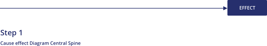
If the effect is too general a statement, it will be interpreted quite differently by the various people involved. The contributions will then tend to be diffuse rather than focused. They may bring in considerations that are irrelevant to the problem at hand. For example, “Too many customer complaints are being received by the Customer Service Department” is probably too vague. Spend more time on the analysis of the symptoms so that the specific problem for investigation can be stated more like, “The number of customer complaints about overbooking of flights has doubled in the last year.”
Of course, the effect should also be directly related to the goal statement.
Step 2: Place the Effect
Place the effect or symptom at the right, enclosed in a box. Draw the central spine as a thicker line pointing to it, as in Figure 35.
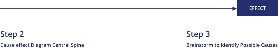
Step 3: Identify Possible Causes
Use brainstorming or a rational step-by-step approach to identify the possible causes. There are two possible approaches to obtaining contributions for the causes to be placed on the diagram: brainstorming and a rational step-by-step approach. You, the team or its leadership will need to make a choice based on an assessment of readiness.
Brainstorming would normally be indicated for a team with a few individuals who are likely to dominate the conversation in a destructive manner or for a team with a few individuals who are likely to be excessively reserved and not make contributions. Also, brainstorming may be best in dealing with highly unusual problems where there will be a premium on creativity.
If one uses brainstorming to identify possible causes, then once the brainstorming is completed, process the ideas generated into the structured order of a cause-effect diagram. This processing will take place in much the same way as described below for the step-by-step procedure, except that the primary source of ideas for inserting in the diagram will come from the list already generated in brainstorming rather than directly from the team members.
If the team members are prepared to work in that environment, a step-by-step approach will usually produce a final product in less time, and the quality of the proposed causal relationships will normally be better.
In the step-by-step procedure, begin by identifying the major causes or classes of causes that will be placed in the boxes at the ends of the main spines coming off the central spine of the diagram.
It may helpful to start with some simple mnemonic lists of possible major areas as a reminder of the many possible sources of causative factors. These lists are characterized as the 5 M’s in manufacturing and the 5 P’s in services, and are as follows:
The 4 W’s can also be used as important guides to a full exploration of the possibilities:
These are just helpful places to start. Start with one of these sets of categories and, after a while, rearrange the results into another set of major areas that fit its particular problem more appropriately.
After identifying the major causes, select one of them and work on it systematically, identifying as many causes of the major cause as possible. Take each of these “secondary” causes and ask whether there are any relevant causes for each of them.
Continue to move systematically down the causal chain within each major or secondary cause until that one is exhausted before moving on to the next one. Ideas may surface that should apply to an area already completed. Be sure to backtrack and add the new idea.
Step 4: Place the Major Causes
Each of the major causes (not less than two and normally not more than six) should be worded in a box and connected with the central spine by a line at an angle of about 70 degrees. Here, as well as in subsequent steps, it has proved useful to use adhesive notes to post the individual main and subsidiary causes about the main spine. Since these notes can be easily attached and moved, it will make the process more flexible and the result easier for the participants to visualize. Figure 36 generalizes the diagram to this point.
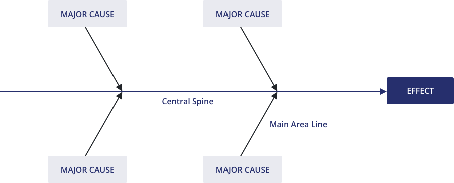
Step 5 (Part A): Add Causes to Main Area
Add causes for each main area. Each factor that is a cause of a main area is placed at the end of a line that is drawn so that it connects with the appropriate main area line and is parallel with the central spine. Figure 37 shows how to display a number of possible causes of problems arising from an engine, which is a main area for some larger symptom that is being explained.
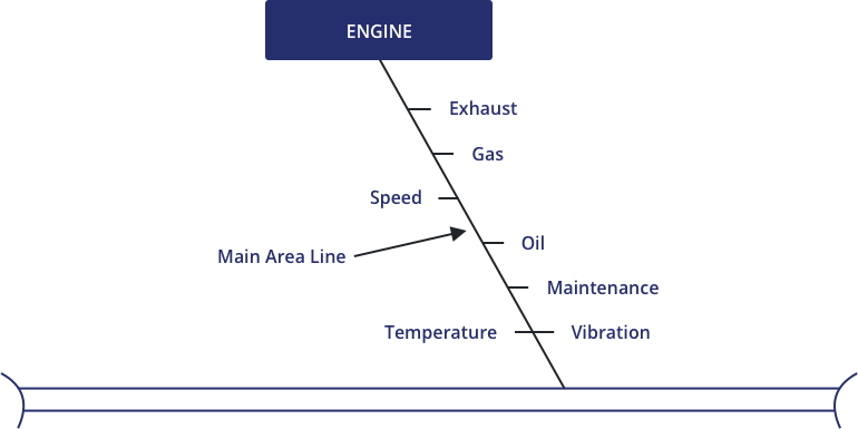
C-E diagrams are generally easier to read and appear more visually pleasing if the text is placed at the end of the line as in Figure 37. Other users have placed the text on the line like Figure 38. Text on the line tends to be harder to use and read, especially as more levels of subsidiary causes are added.
Step 5 (Part B): Less Desirable Placement
Step 6 (part a): add subsidiary causes for each cause.
Add subsidiary causes for each cause already entered. Each of these causes is placed at the end of a line which is drawn (1) to connect with the line associated with the factor that it causes and (2) parallel with either the main area line or the central spine. Figure 39 is an amplification of the portion of a C-E diagram introduced in Step 5. Note how the governor and throttle have been added as possible causes of the wrong speed of the engine. Throttle malfunction may result from either of two causes: Faulty calibration or defective linkage.
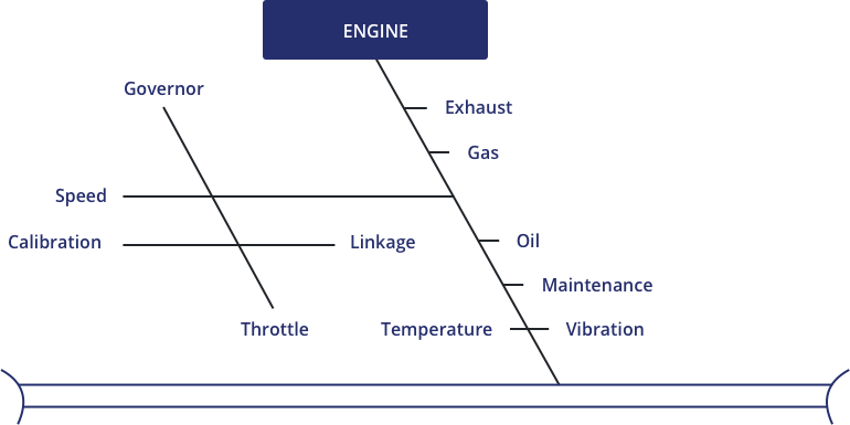
Keeping the lines parallel makes reading easier and the visual effect more pleasing. Clearly, when one is actually working on a C-E diagram in a team meeting, one cannot always keep the lines neat and tidy. In the final documentation, however, it is found that using parallel lines makes for a more satisfactory diagram. A diagram composed of lines with random orientation like the following example is harder to read and looks less professional.
Step 6 (Part B): Less Desirable Placement

Step 7: Continue Adding Possible Causes
Continue adding possible causes to the diagram until each branch reaches a root cause. As the C-E diagram is constructed, team members tend to move back along a chain of events that is sometimes called the causal chain. Teams move from the ultimate effect they are trying to explain, to major areas of causation, to causes within each of those areas, to subsidiary causes of each of those, and so forth. When do they stop? Teams should stop only when the last cause out at the end of each causal chain is a potential root cause.

A root cause has three characteristics that will help explain when to stop. First, it causes the event the team had sought after—either directly or through a sequence of intermediate causes and effects. Second, it is directly controllable. That is, in principle, team members could intervene to change that cause. In the engine example, we have been using in this section, speed cannot be controlled directly. Control of speed is dependent on proper functioning of the throttle and governor, but proper control with the throttle is dependent on correct calibration and proper functioning of the linkage. The calibration and the linkage can be controlled. They are root causes.
Third, and finally, as the result of the other two characteristics, if the theory embodied in a particular entry on the diagram is proved to be true, then the elimination of that potential root cause will result in the elimination or reduction of the problem effect that we were trying to explain.
Step 8: Check Logical Validity of Each Causal Chain
Check the logical validity of each causal chain. Once the entire C-E diagram is complete, it is wise to start with each potential root cause and “read” the diagram forward to the effect being explained. Be sure that each causal chain makes logical and operational sense. Consider the following example, which is a portion of a C-E diagram seeking to explain errors in an order-entry process. One main area of errors concerns errors in the part numbers. Sales representatives look up the part in a catalog and enter the part number on an order form. The information from the form is then keyed into a database.
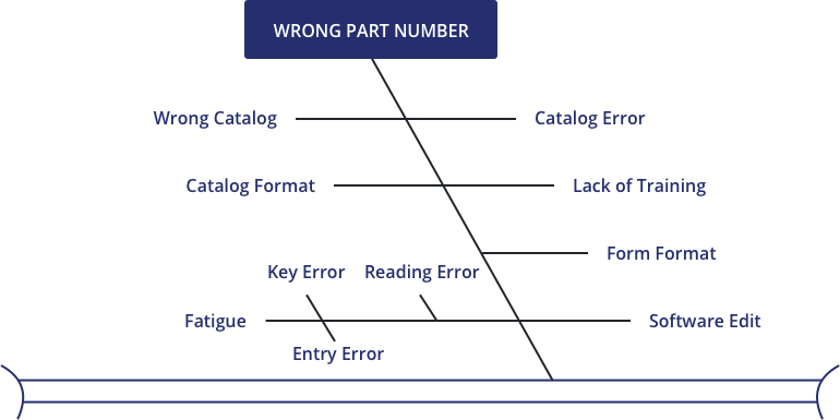
Start with the proposed root cause “keying error.” Then read it as follows: “Keying errors cause fatigue which causes the wrong part numbers…” Once we try to read the diagram, the problem becomes clear. Keying errors do not cause fatigue; fatigue causes keying errors, and the diagram should be reorganized as follows.
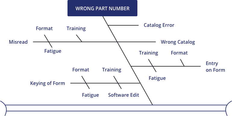
This redrawn diagram places fatigue, format, and training as root causes of three different intermediate causes of the wrong part numbers —misreading the catalog, entering the data on the form improperly, and keying the data improperly. Because these now trace out logical causal chains, it is easier to devise effective ways of testing the theories. For example, form formats which cause problems in keying may differ from those which create problems in the original pencil entry.
The general “lack of training” cause on the original diagram is normally a good danger sign that the causal chain needs to be checked. Lack of training in reading the catalog will create reading errors, but if the errors come at the keying stage, no amount of training on use of the catalog will do any good. Whenever one sees “lack of training” (or lack of anything else for that matter) on a C-E diagram, one should ask two questions. First, exactly which skill is training lacking in? And second, how does that lack cause the factor being explained at the moment? As we saw in our example here, answers to those questions may help identify missing intermediate causal factor and causal relationships that are stated backward.
Step 9: Check for Completeness
As discussed more fully in the interpretation section, check for the following:
- Main branches with fewer than three causes
- Main branches with substantially fewer causes than most others
- Main branches that go into less detail, with fewer levels of subsidiary causes than do the others
- Main branches that have substantially more causes than most of the others
The existence of one of these conditions does not automatically mean a defect in the diagram; it merely suggests that further investigation is warranted. At this point, it is also good to double check that the 4 W’s, 5 M’s, and/or 5 P’s are considered as appropriate.
When to Use Cause and Effect Diagrams
Formulating theories.
The chief application of the cause-effect diagram is for the orderly arrangement of theories about the causes of the observed quality problem that the team is assigned to resolve. Once the theories are well understood and ordered, then the team will use its best collective judgment to identify those theories which should be tested. The final objective of the characterize step is the identification of the primary root cause or causes of the team’s problem.
There are also other opportunities for organizing theories. The team may want to know why some part of the process works better than other parts. For example:
- Why does automobile A obtain ten percent better mileage per gallon than all other similar vehicles tested?
- Why is the productivity of assembly line B always higher than the productivity of the other lines?
Designing for Culture
During the Improve step, the cause-effect diagram may also be useful for the team in considering the cultural impact of its proposed remedy. A cause-effect diagram can sometimes be helpful in thinking systematically about the resistance that the proposed solution is likely to meet. If the phenomenon to be explained is resistance to the proposed remedy, then the team can construct a cause-effect diagram to help identify the most important resistances it will need to address.
How to Interpret Cause and Effect Diagrams
The cause-effect diagram does not provide an answer to a question, as some other tools do. Its main value is to serve as a vehicle for producing, in a very focused manner, a list of all known or suspected causes which potentially contribute to the observed effect. At the time of generating the cause-effect diagram, it is not usually known whether these causes are responsible for the effect or not.
A well-prepared cause-effect diagram is a superb vehicle for helping to reach a common understanding of a complex problem, with all its elements and relationships clearly visible at whatever level of detail is required. The output of the diagram can be leveraged by prioritizing potential causes or theories for further investigation.
The Difference between Theory and Fact
We have noted that cause-effect diagrams present and organize theories. Only when theories are tested with data can we prove causes of observed phenomena. The cause-effect diagram helps organize the search for the causes, but it does not identify the causes. Other tools, such as Pareto analysis , scatter diagrams, and histograms, will be used to analyze data to establish the causality empirically.
Checking for Completeness
As a cause-effect diagram is constructed, it should be reviewed for completeness. There can be no exact rules for this review, but some guidelines are helpful. Some of these are discussed in more detail in the construction section.)
Be certain that you have at least asked how each of the 4 W’s and each of the 5 M’s or 5 P’s might apply to the effect.
Generally, each main branch of the diagram will have at least three or four additional branches. If one does not, further consideration of that branch may be advisable to verify that it has been understood fully.
If some main branches have substantially fewer causes attached to them, or if the causes on them do not go back as many steps in the causal chain, you may not have as full an understanding of that element of the process as you do of the others. It may be appropriate to seek theories from additional persons familiar with that element of the process.
If some branches appear overloaded with causes compared to the others, consider whether they might be most appropriately divided into two or more main branches.
Verify that the cause at the end of each causal chain is potentially a root cause. Such a potential root cause will normally satisfy three conditions. (1) You can trace a logical causal relationship from that cause, through all its intermediate causes, to the final effect being explained. (2) That cause is, in principle, directly controllable. (3) Therefore, if shown to be true, that cause could be eliminated, and the effect would disappear or be reduced.
Potential Pitfalls and Problems in Interpretation
The most serious possible misinterpretation of a cause-effect diagram is to confuse this orderly arrangement of theories with real data. The C-E diagram is a powerful and useful way to develop theories, display them, and test their logical consistency. It is no substitute for empirical testing of the theories.
We will discuss in more detail later the need to test each causal relation in the C-E diagram for logical consistency. Failure to make those checks can greatly reduce the usefulness of the diagram and often lead to the waste of valuable time collecting and analyzing the wrong information.
Another common pitfall is to begin construction of the diagram before the symptoms have been analyzed as thoroughly as existing information will permit. In such cases, the effect being explained may be so general and ill-defined that the team will have a hard time focusing and the resulting diagram may be unnecessarily large, complex, and difficult to use. A clear and precisely articulated effect will produce more relevant theories, better causal relationships, and a more effective model for the selection and testing of theories.
A final pitfall is to limit the theories that are proposed and considered. While the symptom being explained should be as precisely defined as possible, the team must seek to develop just as many theories as possible about its causes. If a team does not develop a wide-ranging set of theories, they might miss their most serious root cause.
What Is Done Next?
With a complete and logical set of theories in hand, the team will now want to discover which are the principal root causes. This structured approach to identify theories allows investigation of those of importance rather than wasting time on trivial theories. One or more of these theories will be selected for testing, collect the data needed for the test, and apply one or more other tools to these data to either confirm or deny the tested theories.
Cause & Effect Diagram Template
Use this template to complete 5-why analysis and proceed to create a cause-effect diagram.
To use the template:
- Download the Cause Effect Diagram Template .
- Place the effect or symptom in the Effect box.
- Identify the potential causes and place them in the cause boxes.
- Add subsidiary causes under the main cause, keep adding subsidiary causes until you reach a root cause.
- Check the validity of each cause.
For more information on Cause and Effect Diagrams and how Juran can help you leverage it to improve your quality and productivity, please get in touch with the team.
Leave a Reply Cancel reply
You must be logged in to post a comment.
Recommended Reading
Juran daily kata, quality 4.0: revolutionizing quality in manufacturing through digital transformation, the art of agile and scrum.

IMAGES
VIDEO
COMMENTS
The Cause and Effect Diagram is a versatile tool that can be used in various problem-solving and improvement initiatives, including quality management, process improvement, root cause analysis, and project management. It encourages collaboration, brainstorming, and structured analysis, enabling teams to gain deeper insights into complex ...
Cause and Effect Diagram is a graphical representation that illustrates the cause-and-effect relationships within a system or a specific problem. Developed by Kaoru Ishikawa, this diagram is widely used in various industries to analyze complex issues and facilitate effective problem-solving. The diagram gets its name from its fishbone-like ...
Cause and effect diagrams start with the effect at the center of the diagram, represented by a box or a circle. Then, branches get drawn out from the center, representing possible causes of the effect. This helps teams to identify multiple factors that contribute to an observed effect. Each branch is a category of causes, such as "manpower ...
A fishbone diagram is a problem-solving approach that uses a fish-shaped diagram to model possible root causes of problems and troubleshoot possible solutions. It is also called an Ishikawa diagram, after its creator, Kaoru Ishikawa, as well as a herringbone diagram or cause-and-effect diagram. Fishbone diagrams are often used in root cause ...
Professor Kaoru Ishikawa created Cause and Effect Analysis in the 1960s. The technique uses a diagram-based approach for thinking through all of the possible causes of a problem. This helps you to carry out a thorough analysis of the situation. There are four steps to using the tool. Identify the problem.
The Fishbone Diagram, also known by various other names such as Ishikawa Diagram, Cause and Effect Diagram or 6Ms, is a visual tool used in problem-solving and root cause analysis.Originating from the quality management sector, it is used as a systematic approach to identify, explore, and display possible causes of a specific problem.
Also called: cause-and-effect diagram, Ishikawa diagram. This cause analysis tool is considered one of the seven basic quality tools. The fishbone diagram identifies many possible causes for an effect or problem. It can be used to structure a brainstorming session. It immediately sorts ideas into useful categories.
A fishbone diagram, also known as cause and effect diagrams, Ishikawa diagram and Herringbone diagram, is a visualization tool used to find the root cause of a problem. It helps you group all the potential causes of a problem in a structured way to find the ultimate cause of your problem. Kaoru Ishikawa invented this diagram in the 1960s to use ...
The Fishbone Diagram is a visual tool used in Lean Six Sigma to identify root causes of problems. It resembles a fish skeleton, with the main problem at the head and potential causes branching off the spine into categories, facilitating a systematic approach to problem-solving. Also commonly known as a Cause and Effect Diagram or an Ishikawa ...
Step 1 - Define the problem. The first step to solving any problem - and the key to learning how to make a fishbone diagram - is correctly defining it. A clearly defined problem makes it easier to identify causes. It also encourages us to determine whether there's even a problem to begin with. In this case, the problem we've ...
A fishbone diagram is a visualization tool, developed by Dr. Kaoru Ishikawa, a quality control specialist, for identifying the root causes of a problem, categorizing them, and generating solutions. Also called the Ishikawa diagram, or cause and effect diagram, the fishbone analysis is often used in troubleshooting and product development ...
The tool helps in identifying the potential causes that could have caused the problem. A sample fishbone diagram looks like this: It is called a fishbone as it looks like the skeleton of a fish. The head of the fish explains the problem statement (or the effect) and the bones attached explain the possible cause and sub-causes.
The Ishikawa fishbone diagram or just fishbone diagram, named after its creator Kaoru Ishikawa, is a powerful visualization tool designed to map out causal relationships concerning a particular problem or issue. Its unique design, reminiscent of a fish's skeletal structure, places the primary problem or effect at the fish's head.
The best way to understand cause and effect diagrams is to look at some examples of cause and effect diagrams. Click on any of these cause and effect diagrams included in SmartDraw and edit them: Blank Cause & Effect Template 5 Whys Fishbone Diagram Basic Ishikawa Diagram. Browse SmartDraw's entire collection of cause and effect examples and ...
A cause and effect diagram is a visual map that functions as a problem-solving tool. As the name suggests, its main purpose is to help you identify the cause of a troubling situation in relation to the effect (or results) you've observed. To clarify the cause and effect diagram definition further, it may help to understand that this tool is ...
Solving Problems With Cause and Effect Analysis. Cause and Effect Analysis is a technique that helps you identify all the likely causes of a problem. This means that you can find and fix the main cause, first time around, without the problem running on and on. The diagrams you create with this type of analysis are sometimes known as fishbone ...
The 5 Whys can be used individually or as a part of the fishbone (also known as the cause and effect or Ishikawa) diagram. The fishbone diagram helps you explore all potential or real causes that result in a single defect or failure. Once all inputs are established on the fishbone, you can use the 5 Whys technique to drill down to the root causes.
The cause and effect analysis uses brainstorming and critical analysis by way of visual representation to enable problem-solving. The main problem is drawn out on the left while the main causes are drawn out an extension of the problem. This then calls for a look at the sub causes which are written out as branches of the main problems.
Professor Kaoru Ishikawa created Cause and Effect Analysis in the 1960s. The technique uses a diagram-based approach for thinking through all of the possible causes of a problem. This helps you to carry out a thorough analysis of the situation. There are four steps to using the tool. Identify the problem.
1. Cause and effect diagrams are a powerful problem-solving technique that can help you identify the root cause of any issue, from small everyday annoyances to complex organizational problems. By following a systematic process of gathering data, analyzing it and then developing solutions, cause and effect diagrams can be used to effectively ...
A cause-effect diagram is a visual tool used to logically organize possible causes for a specific problem or effect by graphically displaying them in increasing detail, suggesting causal relationships among theories. A popular type is also referred to as a fishbone or Ishikawa diagram. Cause-Effect can also be diagrammed using a tree diagram.
Ishikawa diagrams (also called fishbone diagrams, herringbone diagrams, cause-and-effect diagrams) are causal diagrams created by Kaoru Ishikawa that show the potential causes of a specific event.. Common uses of the Ishikawa diagram are product design and quality defect prevention to identify potential factors causing an overall effect. Each cause or reason for imperfection is a source of ...
The Cause and Effect Diagram is a valuable tool for problem-solving, as it offers many advantages. It can help you visualize the problem and its causes, making them easier to comprehend and explain.